
Datasheet


LT4180
12
4180fb
For more information www.linear.com/4180
applicaTions inForMaTion
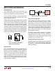
Figure 9. Voltage Divider for Output Voltage, UVL and OVL
The voltage divider resistors can be calculated from the
following equations:
R
T
=
V
OV
200µA
, R4 =
1.22V
200µA
Where R
T
is the total divider resistance and V
OV
is the
overvoltage set point.
Find the equivalent series resistance for R2 and R3 (R
SER-
IES
). This resistance will determine the RUN voltage level.
R
SERIES
=
1.22 • R
T
V
UVL
⎛
⎝
⎜
⎞
⎠
⎟
−R4
R1= R
T
−R
SERIES
−R4
R3 =
1.22V − V
OUT(NOM)
•
R4
R
T
⎛
⎝
⎜
⎞
⎠
⎟
V
OUT(NOM)
R
T
R2 = R
SERIES
−R3
Where V
UVL
is the RUN voltage and V
OUT(NOM)
is the
nominal output voltage desired.
For example, with V
UVL
= 4V, V
OV
= 7.5V and V
OUT(NOM)
= 5V,
R
T
=
7.5V
200µA
= 37.5k
R4 =
1.22V
200µA
= 6.1k
R
SERIES
=
1.22V • 37.5k
4V
⎛
⎝
⎜
⎞
⎠
⎟
− 6.1k = 5.34k
R1 = 37.5k − 5.34k − 6.1k = 26.06k
R3 =
1.22 V −
5V • 6.1k
37.5k
⎛
⎝
⎜
⎞
⎠
⎟
5V
37.5k
= 3.05k
R2 = R
SERIES
− R3 = 2.29k
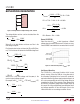
R
SENSE
SELECTION
Select the value of R
SENSE
so that it produces a 100mV
voltage drop at maximum load current. For best accuracy,
V
IN
and SENSE should be Kelvin connected to this resistor.
Figure 10. Soft-Correct Operation, C
HOLD4
= 1µF
R3
FB
4180 F09
RUN
R2
LT4180
R4
OV
R1
V
IN
200ms/DIV
4180 F08
5V
POWER SUPPLY
OUTPUT VOLTAGE
10Vw
POWER SUPPLY
INPUT VOLTAGE
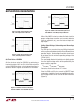
Soft-Correct Operation
The LT4180 has a soft-correct function which insures
orderly start-up. When the RUN pin rising threshold is
first exceeded (indicating V
IN
has crossed its undervolt-
age lockout threshold), power supply output voltage is set
to a value corresponding to zero wiring voltage drop (no
correction for wiring). Over a period of time (determined
by CHOLD4), the power supply output voltage ramps up
to account for wiring voltage drops, providing best load-
end voltage regulation. A new soft-correct cycle is also
initiated whenever an overvoltage condition occurs.