
Datasheet
LT8302
15
Rev E
For more information www.analog.com
APPLICATIONS INFORMATION
Turns Ratio
Note that when choosing an R
FB
/R
REF
resistor ratio to set
output voltage, the user has relative freedom in selecting
a transformer turns ratio to suit a given application. In
contrast, the use of simple ratios of small integers, e.g.,
3:1, 2:1, 1:1, etc., provides more freedom in settling total
turns and mutual inductance.
Typically, choose the transformer turns ratio to maximize
available output power. For low output voltages (3.3V
or 5V), a N:1 turns ratio can be used with multiple pri-
mary windings relative to the secondary to maximize the
transformer’s current gain (and output power). However,
remember that the SW pin sees a voltage that is equal
to the maximum input supply voltage plus the output
voltage multiplied by the turns ratio. In addition, leakage
inductance will cause a voltage spike (V
LEAKAGE
) on top of
this reflected voltage. This total quantity needs to remain
below the 65V absolute maximum rating of the SW pin to
prevent breakdown of the internal power switch. Together
these conditions place an upper limit on the turns ratio,
N
PS
, for a given application. Choose a turns ratio low
enough to ensure
N
PS
<
65V – V
IN(MAX)
– V
LEAKAGE
V
OUT
+ V
F
For larger N:1 values, choose a transformer with a larger
physical size to deliver additional current. In addition,
choose a large enough inductance value to ensure that
the switch-off time is long enough to accurately sample
the output voltage.
For lower output power levels, choose a 1:1 or 1:N trans
-
former for the absolute smallest transformer size. A 1:N
transformer will minimize the magnetizing inductance
(and minimize size), but will also limit the available output
power. A higher 1:N turns ratio makes it possible to have
very high output voltages without exceeding the break
-
down voltage of the internal power switch.
The turns ratio is an important element in the isolated
feedback scheme, and directly affects the output voltage
accuracy. Make sure the transformer manufacturer speci-
fies turns ratio accuracy within ±1%.
Saturation Current
The current in the transformer windings should not exceed
its rated saturation current. Energy injected once the core
is saturated will not be transferred to the secondary and
will instead be dissipated in the core. When designing
custom transformers to be used with the LT8302, the
saturation current should always be specified by the
transformer manufacturers.
Winding Resistance
Resistance in either the primary or secondary windings
will reduce overall power efficiency. Good output volt
-
age regulation will be maintained independent of winding
resistance due to the boundary/discontinuous conduction
mode operation of the LT8302.
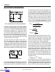
Leakage Inductance and Snubbers
Transformer leakage inductance on either the primary
or secondary causes a voltage spike to appear on the
primary after the power switch turns off. This spike is
increasingly prominent at higher load currents where
more stored energy must be dissipated. It is very impor-
tant to minimize transformer leakage inductance.
When designing an application, adequate margin should
be kept for the worst-case leakage voltage spikes even
under overload conditions. In most cases shown in
Figure5, the reflected output voltage on the primary plus
V
IN
should be kept below 50V. This leaves at least 15V
margin for the leakage spike across line and load condi
-
tions. A larger voltage margin will be required for poorly
wound transformers or for excessive leakage inductance.
Downloaded from Arrow.com.Downloaded from Arrow.com.Downloaded from Arrow.com.Downloaded from Arrow.com.Downloaded from Arrow.com.Downloaded from Arrow.com.Downloaded from Arrow.com.Downloaded from Arrow.com.Downloaded from Arrow.com.Downloaded from Arrow.com.Downloaded from Arrow.com.Downloaded from Arrow.com.Downloaded from Arrow.com.Downloaded from Arrow.com.Downloaded from Arrow.com.