
Datasheet

LT8302
19
Rev E
For more information www.analog.com
APPLICATIONS INFORMATION
Example:
D =
5V
+
0.3V
( )
• 3
5V + 0.3V
( )
• 3 + 12V
= 0.57
I
SW
=
5V • 1.5A • 2
0.8 • 12V • 0.57
f
SW
= 277kHz
The transformer also needs to be rated for the correct
saturation current level across line and load conditions.
A saturation current rating larger than 7A is necessary
to work with the LT8302. The 750311564 from Würth is
chosen as the flyback transformer.
Step 3: Choose the output diode.
Two main criteria for choosing the output diode include
forward current rating and reverse-voltage rating. The
maximum load requirement is a good first-order guess
at the average current requirement for the output diode.
Under output short-circuit condition, the output diode
needs to conduct much higher current. Therefore, a con-
servative metric is 60% of the maximum switch current
limit multiplied by the turns ratio:
I
DIODE(MAX)
= 0.6 • I
SW(MAX)
• N
PS
Example:
I
DIODE(MAX)
= 8.1A
Next calculate reverse voltage requirement using maxi-
mum V
IN
:
V
REVERSE
= V
OUT
+
V
IN(MAX)
N
PS
Example:
V
REVERSE
= 5V +
32V
3
= 15.7V
The PDS835L (8A, 35V diode) from Diodes Inc. is chosen.
Step 4: Choose the output capacitor.
The output capacitor should be chosen to minimize the
output voltage ripple while considering the increase in size
and cost of a larger capacitor. Use the following equation
to calculate the output capacitance:
C
OUT
=
L
PRI
•I
SW
2
2 • V
OUT
• ΔV
OUT
Example:
Design for output voltage ripple less than ±1% of V
OUT
,
i.e., 100mV.
C
OUT
=
9µH • 4.5A
( )
2
2 • 5V • 0.1V
= 182µF
Remember ceramic capacitors lose capacitance with
applied voltage. The capacitance can drop to 40% of
quoted capacitance at the maximum voltage rating. So
a 220µF, 6.3V rating X5R or X7R ceramic capacitor is
chosen.
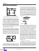
Step 5: Design snubber circuit.
The snubber circuit protects the power switch from leak
-
age inductance voltage spike. A (RC + DZ) snubber is
recommended for this application. A 470pF capacitor in
series with a 39Ω resistor is chosen as the RC snubber.
The maximum Zener breakdown voltage is set according
to the maximum V
IN
:
V
ZENNER(MAX)
≤ 60V – V
IN(MAX)
Example:
V
ZENNER(MAX)
≤ 60V – 32V = 28V
A 24V Zener with a maximum of 26V will provide optimal
protection and minimize power loss. So a 24V, 1.5W Zener
from Central Semiconductor (CMZ5934B) is chosen.
Choose a diode that is fast and has sufficient reverse volt-
age breakdown:
V
REVERSE
> V
SW(MAX)
V
SW(MAX)
= V
IN(MAX)
+ V
ZENNER(MAX)
Example:
V
REVERSE
> 60V
A 100V, 1A diode from Diodes Inc. (DFLS1100) is chosen.
Downloaded from Arrow.com.Downloaded from Arrow.com.Downloaded from Arrow.com.Downloaded from Arrow.com.Downloaded from Arrow.com.Downloaded from Arrow.com.Downloaded from Arrow.com.Downloaded from Arrow.com.Downloaded from Arrow.com.Downloaded from Arrow.com.Downloaded from Arrow.com.Downloaded from Arrow.com.Downloaded from Arrow.com.Downloaded from Arrow.com.Downloaded from Arrow.com.Downloaded from Arrow.com.Downloaded from Arrow.com.Downloaded from Arrow.com.Downloaded from Arrow.com.