
Datasheet


LT8582
10
8582f
OPERATION
OPERATION – OVERVIEW
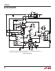
The LT8582 uses a constant frequency, current mode control
scheme to provide excellent line and load regulation. Each
channel’s undervoltage lockout (UVLO) function, together
with soft-start and frequency foldback, offer a controlled
means of starting up. Fault features are incorporated into
each channel of the LT8582 to facilitate the detection of
output shorts, overvoltage and overtemperature condi-
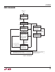
tions. Please refer to the Block Diagram (Figure 1) and
the State Diagram (Figure 2) for the following description
of the part’s operation.
OPERATION – START-UP
Several functions are provided to enable a very clean
start-up of both channels of the LT8582.
Precise Turn-On Voltage
The SHDN pin on each channel is compared to an internal
voltage reference to give a precise turn on voltage level. Tak-
ing each SHDN pin above 1.31V enables the corresponding
channel. Taking each SHDN pin below 300mV shuts down
the channel, resulting in extremely low quiescent current
for that channel. The SHDN pin has 35mV of hysteresis
to protect against glitches and slow ramping.
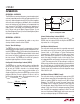
Configurable Undervoltage Lockout (UVLO)
The SHDN pin can also be used to create a configurable
UVLO for each channel. This function sets the turn on/
off of each of LT8582’s channels at a desired voltage
(VIN
UVLO
). Figure 3 shows how a resistor divider (or a
single resistor) from V
IN
to the SHDN pin can be used to
program VIN
UVLO
. R
UVLO2
is optional. If left out, set it to
infinite in the equation below. For increased accuracy, set
R
UVLO2
≤ 10k. Pick R
UVLO1
as follows:
VIN
UVLO
R
UVLO1
=
–1.31V
1.31V
R
UVLO2
⎛
⎝
⎜
⎞
⎠
⎟
+ 12.3µA
Internal Undervoltage Lockout (UVLO)
Regardless of where external circuitry sets VIN
UVLO
, the
LT8582 also has internal UVLO circuitry that disables the
chip when V
IN
< 2.3V (typical).
Soft-Start of Switch Current
The soft-start circuitry provides for a gradual ramp-up of
the switch current in each channel (refer to Commanded
Current Limit vs SS Voltage in Typical Performance
Characteristics). When the channel is taken out of shut-
down, the external SS capacitor is first discharged. This
resets the state of the logic circuits in the channel. Then
an integrated 250k resistor pulls the channel’s SS pin to
~1.84V. The ramp rate of the SS pin voltage is set by this
250k resistor and the external capacitor connected to this
pin. Once SS gets to ~1.84V, the CLKOUT pin is enabled
and an internal regulator pulls the pin up quickly to ~2.1V.
Typical values for the external soft-start capacitor range
from 100nF to 1F.
Soft-Start of External PMOS (if used)
The soft-start circuitry also gradually ramps up the GATE
pin pull-down current for the corresponding channel. This
allows an external PMOS to slowly turn on (M1 in Block
Diagram). The GATE pin current increases linearly with
SS voltage, with a maximum current of 1mA when the
SS voltage gets above 550mV. Note that if the GATE pin
voltage is less than 2V for SS voltages exceeding 550mV,
then the GATE pin impedance to ground is 2k. The soft
turn on of the external PMOS helps limit inrush current at
start up, making hot plugs of LT8582s feasible.
Figure 3. Configurable UVLO
1.31V
GND
ACTIVE/
LOCKOUT
SHDN
8582 F03
V
IN
V
IN
R
UVLO2
(OPTIONAL)
R
UVLO1
–
+
12.3µA
AT 1.31V