
Datasheet

LT8614
9
Rev. E
For more information www.analog.com
PIN FUNCTIONS
BIAS (Pin 1): The internal regulator will draw current from
BIAS instead of V
IN
when BIAS is tied to a voltage higher
than 3.1V. For output voltages of 3.3V to 30V this pin
should be tied to V
OUT
. If this pin is tied to a supply other
than V
OUT
use a 1µF local bypass capacitor on this pin. If
no supply is available, tie to GND.
INTV
CC
(Pin 2): Internal 3.4V Regulator Bypass Pin. The
internal power drivers and control circuits are powered
from this voltage. INTV
CC
maximum output current is
20mA. Do not load the INTV
CC
pin with external circuitry.
INTV
CC
current will be supplied from BIAS if BIAS >
3.1V, otherwise current will be drawn from V
IN
. Voltage
on INTV
CC
will vary between 2.8V and 3.4V when BIAS
is between 3.0V and 3.6V. Decouple this pin to power
ground with at least a 1μF low ESR ceramic capacitor
placed close to the IC.
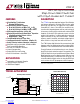
BST (Pin 3): This pin is used to provide a drive voltage,
higher than the input voltage, to the topside power switch.
Place a 0.1µF boost capacitor as close as possible to the
IC.
V
IN1
(Pin 4): The LT8614 requires two 1µF small input
bypass capacitors. One 1µF capacitor should be placed
between V
IN1
and GND1. A second 1µF capacitor should
be placed between V
IN2
and GND2. These capacitors must
be placed as close as possible to the LT8614. A third
larger capacitor of 2.2µF or more should be placed close
to the LT8614 with the positive terminal connected to V
IN1
and V
IN2
, and the negative terminal connected to ground.
See applications section for sample layout.
GND1 (6, 7): Power Switch Ground. These pins are the
return path of the internal bottom side power switch and
must be tied together. Place the negative terminal of the
input capacitor as close to the GND1 pins as possible.
Also be sure to tie GND
1 to the ground plane. See the
Applications Information section for sample layout.
SW (Pins 8, 9): The SW pins are the outputs of the internal
power switches. Tie these pins together and connect them
to the inductor and boost capacitor. This node should be
kept small on the PCB for good performance and low EMI.
GND2 (10, 11): Power Switch Ground. These pins are the
return path of the internal bottom side power switch and
must be tied together. Place the negative terminal of the
input capacitor as close to the GND2 pins as possible.
Also be sure to tie GND
2 to the ground plane. See the
Applications Information section for sample layout.
V
IN2
(Pin 13): The LT8614 requires two 1µF small input
bypass capacitors. One 1µF capacitor should be placed
between V
IN1
and GND1. A second 1µF capacitor should
be placed between V
IN2
and GND2. These capacitors
must be placed as close as possible to the LT8614. A
third larger capacitor of 2.2µF or more should be placed
close to the LT8614 with the positive terminal connected
to V
IN1
and V
IN2
, and the negative terminal connected
to ground. See the Applications Information section for
sample layout.
EN/UV (Pin 14): The LT8614 is shut down when this pin
is low and active when this pin is high. The hysteretic
threshold voltage is 1.00V going up and 0.96V going
down. Tie to V
IN
if the shutdown feature is not used. An
external resistor divider from V
IN
can be used to program
a V
IN
threshold below which the LT8614 will shut down.
RT (Pin 15): A resistor is tied between RT and ground to
set the switching frequency.
TR/SS (Pin 16): Output Tracking and Soft-Start Pin. This
pin allows user control of output voltage ramp rate during
start-up. A TR/SS voltage below 0.97V forces the LT8614
to regulate the FB pin to equal the TR/SS pin voltage.
When TR/SS is above 0.97V, the tracking function is dis-
abled and the internal reference resumes control of the
error amplifier. An internal 2.2μA pull-up current from
INTV
CC
on this pin allows a capacitor to program output
voltage slew rate. This pin is pulled to ground with an
internal 230Ω MOSFET during shutdown and fault condi-
tions; use a series resistor if driving from a low impedance
output. This pin may be left floating if the tracking function
is not needed.
Downloaded from Arrow.com.Downloaded from Arrow.com.Downloaded from Arrow.com.Downloaded from Arrow.com.Downloaded from Arrow.com.Downloaded from Arrow.com.Downloaded from Arrow.com.Downloaded from Arrow.com.Downloaded from Arrow.com.