
Datasheet


LT8616
15
8616fa
For more information www.linear.com/LT8616
APPLICATIONS INFORMATION
The LT8616 limits the peak switch current in order to protect
the switches and the system from overload faults. The top
switch current limit (I
LIM
) is 4.2A at 0% duty cycle and
decreases linearly to 2.9A at DC = 80% (channel 2 current
limit are 5.5A at 0% duty cycle and 3.7A at DC = 80%).
The inductor value must then be sufficient to supply the
desired maximum output current (I
OUT(MAX)
), which is a
function of the switch current limit (I
LIM
) and the ripple
current.
I
OUT(MAX)
= I
LIM
–
ΔI
L
2
(8)
The peak-to-peak ripple current in the inductor can be
calculated as follows:
ΔI
L
=
V
OUT
L • f
SW
• 1–
V
OUT
V
IN(MAX)
⎛
⎝
⎜
⎞
⎠
⎟
(9)
where f
SW
is the switching frequency of the LT8616, and
L is the value of the inductor. Therefore, the maximum
output current that the LT8616 will deliver depends on
the switch current limit, the inductor value, and the input
and output voltages.
Each channel has a secondary valley current limit. After
the top switch has turned off, the bottom switch carries
the inductor current. If for any reason the inductor current
is too high, the bottom switch will remain on, delaying the
top switch turning on until the inductor current returns
to a safe level. This level is specified as the valley Current
Limit, and is independent of duty cycle. Maximum output
current in the application circuit is limited to this valley
current plus one half of the inductor ripple current.
In most cases current limit is enforced by the top switch.
The bottom switch limit controls the inductor current when
the minimum on-time condition is violated (high input
voltage, high frequency or saturated inductor).
The bottom switch current limit is designed to avoid any
contribution to the maximum rated current of the LT8616.
The optimum inductor for a given application may differ
from the
one indicated by this design guide. A larger value
inductor provides a higher maximum load current and
reduces the output voltage ripple. For applications requir-
ing smaller load currents, the value of the inductor may
be
lower and the LT8616 may operate with higher ripple
current. This allows use of a physically smaller inductor,
or one with a lower DCR resulting in higher efficiency. Be
aware that low inductance may result in discontinuous
mode operation, which further reduces maximum load
current.
For more information about maximum output current
and discontinuous operation, see Linear Technology’s
Application Note 44.
Finally, for duty cycles greater than 50% (V
OUT
/V
IN
> 0.5),
a minimum inductance is required to avoid sub-harmonic
oscillation. See Application Note 19.
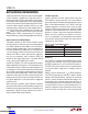
Table 2. Inductor Manufacturers
VENDOR URL
Coilcraft www.coilcraft.com
Sumida www.sumida.com
Toko www.toko.com
Würth Elektronik www.we-online.com
Vishay www.vishay.com
Input Capacitor
Bypass the input of the LT8616 circuit with a ceramic ca-
pacitor of
X7R or X5R type placed as close as possible to
the
V
IN
and GND pins. Y5V types have poor performance
over temperature and applied voltage, and should not be
used. A 2.2μF to 10μF ceramic capacitor is adequate to
bypass the LT8616 and will easily handle the ripple current.
Note that larger input capacitance is required when a lower
switching frequency is used. If the input power source has
high impedance, or there is significant inductance due to
long wires or cables, additional bulk capacitance may be
necessary. This can be provided with a low performance
electrolytic capacitor.
Step-down regulators draw current from the input sup
-
ply in
pulses with very fast rise and fall times. The input
capacitor
is required to reduce the resulting voltage ripple
at the LT8616 and to force this very high frequency
Downloaded from Arrow.com.Downloaded from Arrow.com.Downloaded from Arrow.com.Downloaded from Arrow.com.Downloaded from Arrow.com.Downloaded from Arrow.com.Downloaded from Arrow.com.Downloaded from Arrow.com.Downloaded from Arrow.com.Downloaded from Arrow.com.Downloaded from Arrow.com.Downloaded from Arrow.com.Downloaded from Arrow.com.Downloaded from Arrow.com.Downloaded from Arrow.com.