
Datasheet


LT8616
17
8616fa
For more information www.linear.com/LT8616
APPLICATIONS INFORMATION
source voltage conditions. The V
IN(EN)
threshold prevents
the regulator from operating at source voltages where the
problems might occur. This threshold can be adjusted by
setting the values R5 and R6 (R7, R8 for channel 2) such
that they satisfy the following equation:
R5= R6
V
IN1(EN)
1.03V
–1
⎛
⎝
⎜
⎞
⎠
⎟
(10)
where the
corresponding
channel will remain off until V
IN
is
above V
IN(EN)
. Due to the comparator’s hysteresis, switch-
ing will not stop until the input falls slightly below V
IN(EN)
.
When operating in Burst Mode operation for light load
currents, the current through the V
IN(EN)
resistor network
can easily be greater than the supply current consumed
by the LT8616. Therefore, the V
IN(EN)
resistors should be
large to minimize their effect on efficiency at low loads.
INTV
CC
Regulator
An internal low dropout (LDO) regulator produces the 3.4V
supply from V
IN1
that powers the drivers and the internal
bias circuitry. For this reason, V
IN1
must be present and
valid to use either channel. The INTV
CC
pin supplies cur-
rent for the LT8616’s circuitry and must be bypassed to
ground
with a 1μF ceramic capacitor. Good bypassing is
necessary to supply the high transient currents required
by the power MOSFET gate drivers. To improve efficiency,
the internal LDO will draw current from the BIAS pin when
the BIAS pin is at 3.1V or higher. Typically, the BIAS pin
is tied to the lowest output or external supply above 3.1
V.
If BIAS is connected to a supply other than V
OUT
, bypass
it with a local ceramic capacitor. If the BIAS pin is below
3.0V, the internal LDO will consume current from V
IN1
.
Applications with high input voltage and high switching
frequency where the internal LDO pulls current from V
IN1
will increase die temperature because of the higher power
dissipation across the LDO. Do not connect an external
load to the INTV
CC
pin.
Output Voltage Tracking and Soft-Start
The LT8616 allows the user to program its output voltage
ramp rate with the TR/SS pin. An internal 2μA current pulls
up the TR/SS pin to INTV
CC
. Putting an external capacitor
on TR/SS enables soft starting the output to prevent cur-
rent surge
on the input supply. During the soft-start ramp
the
output voltage will proportionally track the TR/SS pin
voltage. For output tracking applications, TR/SS can be
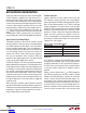
externally driven by another voltage source. From 0V to
0.790V, the TR/SS voltage will override the internal 0.790V
reference input to the error amplifier, thus regulating the
FB pin voltage to that of TR/SS pin (figure 4). When TR/SS
is above 0.790V, tracking
is disabled and the feedback
voltage will regulate to the internal reference voltage. The
TR/SS pin may be left floating if the function is not needed.
Note the LT8616 will not discharge the output to regulate
to a lower TR/SS voltage (figure 5).
An active pull-down circuit is connected to the TR/SS pin
which will discharge the external soft-start capacitor in
the case of fault conditions and restart the ramp when the
faults are cleared. Fault conditions that clear the soft-start
capacitor are the corresponding EN/UV pin below 0.92V,
V
IN1
voltage falling too low, or thermal shutdown.
Figure 4. FB Tracking TR/SS Voltage Until 0.790V
TR/SS VOLTAGE (mV)
0
0
FB VOLTAGE (mV)
600
700
800
500
400
300
200
100
900
600500400300200100 700 800 900 1000
8616 F04
Downloaded from Arrow.com.Downloaded from Arrow.com.Downloaded from Arrow.com.Downloaded from Arrow.com.Downloaded from Arrow.com.Downloaded from Arrow.com.Downloaded from Arrow.com.Downloaded from Arrow.com.Downloaded from Arrow.com.Downloaded from Arrow.com.Downloaded from Arrow.com.Downloaded from Arrow.com.Downloaded from Arrow.com.Downloaded from Arrow.com.Downloaded from Arrow.com.Downloaded from Arrow.com.Downloaded from Arrow.com.