
Datasheet


LT8616
18
8616fa
For more information www.linear.com/LT8616
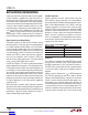
Output Power Good
When the LT8616’s output voltage is within the ±10%
window of the regulation point, which is a FB voltage in
the range of 0.72V to 0.88V (typical), the output voltage
is considered good and the open-drain PG pin goes high
impedance and is typically pulled high with an external
resistor. Otherwise, the internal pull-down device will pull
the PG pin low. To prevent glitching, both the upper and
lower thresholds include 1% of hysteresis. See figure 6.
The PG pin is also actively pulled low during several fault
conditions: corresponding EN/UV pin below 0.92V, INTV
CC
voltage falling too low, V
IN1
UVLO, or thermal shutdown.
APPLICATIONS INFORMATION
Figure 5. TR/SS Does Not Discharge V
OUT
Figure 6. Power-Good Thresholds
Synchronization
To select low ripple Burst Mode operation, tie the SYNC/
MODE pin below 0.4V (this can be ground or a logic low
output). To select pulse skip mode, tie the SYNC/MODE
pin above 2.4V (SYNC/MODE can be tied to INTV
CC
). To
synchronize the LT8616 oscillator to an external frequency
connect a square wave (with 20% to 80% duty cycle) to
the SYNC/MODE pin. The square wave amplitude should
have valleys that are below 0.4V and
peaks above 2.4
V
(up to 6V).
Channel 1 will synchronize its positive switch edge transi
-
tions to the positive edge of the SYNC signal, and channel
2 will synchronize to the negative edge of the SYNC signal.
The LT8616 will not enter Burst Mode operation at low
output loads while synchronized to an external clock, but
instead will pulse skip to maintain regulation. The LT8616
may be synchronized over a 250kHz to 3MHz range. The
R
T
resistor should be chosen to set the LT8616 switching
frequency to 20% below the lowest synchronization input.
For example, if the synchronization signal will be 500kHz
and higher, the R
T
should be selected for 400kHz.
The slope compensation is set by the R
T
value, while the
minimum slope compensation required to avoid subhar-
monic oscillations
is established by the inductor size,
input voltage, and output voltage. Since the synchroniza-
tion frequency
will not change the slopes of the inductor
current waveform, if the inductor is large enough to avoid
subharmonic oscillations at the frequency set by R
T
, then
the slope compensation will be sufficient for all synchro-
nization frequencies.
The
duty cycle of the SYNC signal can be used to set
the relative
phasing of the two channels for minimizing
input ripple.
The
LT8616 does not operate in forced continuous mode
regardless of the SYNC signal. Never leave the SYNC/
MODE pin floating.
2ms/DIV
TR/SS
500mV/DIV
V
OUT
2V/DIV
8616 F05
TEMPERATURE (°C)
–50
–15
PG THRESHOLD RELATIVE TO FB (%)
10
5
0
–5
–10
15
75 100 125 150–25 0 25
8616 F06
50
PG HIGH FALLING
PG LOW RISING
PG HIGH RISING
PG LOW FALLING
Downloaded from Arrow.com.Downloaded from Arrow.com.Downloaded from Arrow.com.Downloaded from Arrow.com.Downloaded from Arrow.com.Downloaded from Arrow.com.Downloaded from Arrow.com.Downloaded from Arrow.com.Downloaded from Arrow.com.Downloaded from Arrow.com.Downloaded from Arrow.com.Downloaded from Arrow.com.Downloaded from Arrow.com.Downloaded from Arrow.com.Downloaded from Arrow.com.Downloaded from Arrow.com.Downloaded from Arrow.com.Downloaded from Arrow.com.