
Datasheet


LT8619/LT8619-5
22
Rev A
For more information www.analog.com
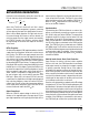
Figure13. Case Temperature Rise vs Load Current Figure14. Case Temperature Rise vs Ambient Temperature
For higher ambient temperatures, care should be taken in
the layout of the PCB to ensure good heat sinking of the
LT8619. The exposed pad on the bottom of the package
must be soldered to a ground plane. This ground should
be tied to large copper layers below with thermal vias;
these layers will spread heat dissipated by the LT8619.
Placing additional vias can reduce thermal resistance fur-
ther. Figure13 shows the rise in case temperature vs load
current. Note that a higher ambient temperature will result
in bigger case temperature rise as shown in Figure14.
Power dissipation within the LT8619 can be estimated
by calculating the total power loss from an efficiency
measurement and subtracting the inductor loss. The
die temperature is calculated by multiplying the LT8619
power dissipation by the thermal resistance from junction
to ambient.
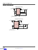
Figure15 shows the typical derating maximum output
current curve. As with any monolithic switching regu-
lator, the PCB layout, thermal resistance, air flow, other
heat sources in the vicinity affect how efficiently heat can
be removed from the die and radically change the die
junction temperature. The actual LT8619 switcher output
voltage and current sourcing capability might deviate from
the performance curve stated in this data sheet. When
pushing the LT8619 to its limit, verify its operation in the
actual environment. AT HIGH AMBIENT TEMPERATURE,
CONTINUOUS OPERATION ABOVE THE MAXIMUM
OPERATION JUNCTION TEMPERATURE MAY IMPAIR
DEVICE RELIABILITY OR PERMANENTLY DAMAGE THE
DEVICE.
Figure15. LT8619 Derating Maximum Output
Current with Junction Temperature Less Than 125°C
APPLICATIONS INFORMATION
V
IN
= 12V
V
OUT
= 5V
f
SW
= 700kHz
T
A
= 25°C
FORCED CONTINUOUS MODE
LOAD CURRENT (A)
0
0.2
0.4
0.6
0.8
1.0
1.2
0
5
10
15
20
CASE TEMPERATURE RISE (°C)
8619 F13
V
IN
= 12V
V
OUT
= 5V, 1.2A LOAD
f
SW
= 700kHz
CONTINUOUS OPERATION ABOVE
MAXIMUM JUNCTION TEMPERATURE
MAY PERMANENTLY DAMAGE THE DEVICE
AMBIENT TEMPERATURE (°C)
25
50
75
100
125
0
5
10
15
20
25
30
35
CASE TEMPERATURE RISE (°C)
8619 F14
V
IN
= 12V
V
OUT
= 3.3V
T
J(MAX)
≤ 125°C
FORCED CONTINUOUS MODE
AMBIENT TEMPERATURE (°C)
90
95
100
105
110
115
120
125
0
0.2
0.4
0.6
0.8
1.0
1.2
1.4
MAXIMUM OUTPUT CURRENT (A)
8619 F15
f
SW
= 700kHz
f
SW
= 2MHz
Downloaded from Arrow.com.Downloaded from Arrow.com.Downloaded from Arrow.com.Downloaded from Arrow.com.Downloaded from Arrow.com.Downloaded from Arrow.com.Downloaded from Arrow.com.Downloaded from Arrow.com.Downloaded from Arrow.com.Downloaded from Arrow.com.Downloaded from Arrow.com.Downloaded from Arrow.com.Downloaded from Arrow.com.Downloaded from Arrow.com.Downloaded from Arrow.com.Downloaded from Arrow.com.Downloaded from Arrow.com.Downloaded from Arrow.com.Downloaded from Arrow.com.Downloaded from Arrow.com.Downloaded from Arrow.com.Downloaded from Arrow.com.