
Datasheet


7
LTC1045
1045fc
Because of this diode, V
OH
must not be greater than V
+
.
Lastly, the maximum voltage between any two power
supply pins must not exceed 15V operating or 18V abso-
lute maximum. For example, if V
+
= 5V, V
–
or V
OL
should
be no more negative than –10V. Note that V
OL
should not
be more negative than –10V even if the V
OH
to V
OL
differential does not exceed the 15V maximum. In this
case the V
+
to V
OL
differential sets the limit.
Input Voltage
The LTC1045 has no upper clamp diodes as do conven-
tional CMOS circuits. This allows the inputs to exceed the
V
+
supply. The inputs will break down approximately 30V
above the V
–
supply. If the input current is limited with
100kΩ, the input voltage can be driven to at least ±50V
with no adverse effects for any combination of allowed
APPLICATIONS INFORMATION
WUU
U
power supply voltages. Output levels will be correct even
under these conditions (i.e., if the input voltage is above
the trip point, the output will be high and if it is below, the
output will be low).
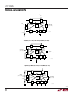
Output Drive
Output drive characteristics of the LTC1045 will vary with
the power supply voltages that are chosen. Output imped-
ance is affected by V
+
, V
OH
and V
OL
. V
–
has no effect on
output impedance. Guaranteed drive characteristics are
specified in the table of electrical characteristics for
V
+
= V
OH
= 5V and V
–
= V
OL
= 0V. Figures 6 and 7 show
relative output impedance for other supply combinations.
In general, output impedance is minimized if V
+
to V
OH
is
minimized and V
OH
to V
OL
is maximized.
V
+
– V
OH
(V)
02
R
OH
/[R
OH
AT (V
OH
– V
OL
) = 5V AND (V
+
– V
OH
) = 0V]
16
1045 F06
4 6 10 14
8
12
4
3
2
1
0
SPECIFIED POINT
V
OH
– V
OL
= 5V
V
OH
– V
OL
= 10V
V
OH
– V
OL
= 4V
V
OH
– V
OL
= 3V
V
OH
– V
OL
(V)
02
R
OL
/[R
OL
AT (V
OH
– V
OL
) = 5V]
16
1045 F07
4 6 10 14
8
12
2
1
0
SPECIFIED POINT
Figure 6. Relative Output Sourcing
Resistance (R
OH
) vs V
+
– V
OH
Figure 7. Relative Output Sinking
Resistance (R
OL
) vs V
OH
– V
OL