
Datasheet


9
LTC1051/LTC1053
10513fa
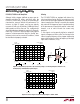
2. If we arbitrarily accept that “aliasing” occurs when
output alias signals reach an amplitude of 0.01% or more
of the output signal, then: the approximate minimum
frequency of an AC input signal which will cause aliasing
is equal to the internal clock frequency multiplied by the
square root of the op amp feedback factor. For instance,
with closed-loop gain of –10, the feedback factor is 1/11
and if f
CLK
= 2.6kHz, alias signals can be detected when
the frequency of the input signal exceeds 750Hz to 800Hz
(Figure 5a).
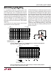
3. The number of alias signals increases when the input
signal frequency increases (Figure 5b).
4. When the frequency, f
IN
, of the input signal is less than
f
CLOCK
, the alias signal(s) amplitude(s) directly scale with
the amplitude of the incoming signal. The output “signal to
alias ratio” cannot be increased by just boosting the input
signal amplitude. However, when the input AC signal
frequency well exceeds the clock frequency, the amplitude
of the alias signals does not directly scale with the input
amplitude. The “signal to alias ratio” increases when the
output swings closely to the rails. (See Figure 5b and
Figure 7.) It is important to note that the LTC1051/
LTC1053 op amps, under light loads (R
L
≥ 10k), swing
closely to the supply rails without generating harmonic
distortion (Figure 8).
B: MAG
RANGE: 9dBV
STATUS: PAUSED
RMS: 25
13dBV
15dB
/DIV
–107
CENTER: 2 625Hz
X: 2535Hz
BW: 19.097Hz
Y: –74.16dBV
SPAN: 2 000Hz
f
IN
= 2.685kHz
f
CLK
2f
CLK
– f
IN
83.5dB
–
+
1/2
LTC1051
1051/53 F05a
10k
10k
0.1µF
0.1µF
50pF
5V
–5V
NOTE: THE f
CLK
– f
IN
= 85Hz
ALIAS FREQUENCY IS 95dB
DOWN FROM THE OUTPUT LEVEL
V
IN
= 10kHz
8V
P-P
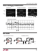
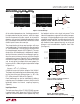
Figure 6b. Output Voltage Spectrum of 1/2 LTC1051 Operating as a Unity-Gain Inverting Amplifier.
V
S
= ±5V, R
L
= 10k, C
L
= 50pF, V
IN
= 8V
P-P
, 10kHz
Figure 6a. Output Voltage Spectrum of 1/2 LTC1051 Operating as a Unity-Gain Inverting Amplifier.
V
S
= ±5V, R
L
= 10k, C
L
= 50pF, V
IN
= 8V
P-P
, 2.685kHz
B: MAG
RANGE: 9dBV
STATUS: PAUSED
RMS: 50
13dBV
15dB
/DIV
–107
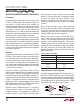
CENTER: 10 000Hz
X: 10000Hz
BW: 95.485Hz
Y: 7.98dBV
SPAN: 10 000Hz
f
IN
= 10kHzf
IN
– f
CLK
2 • f
CLK
6f
CLK
– f
IN
80dB
15dB
1kHz
5f
CLK
– f
IN
f
IN
– 2f
CLK
NOTE: ALL ALIAS FREQUENCY
80dB TO 84dB DOWN FROM OUTPUT
APPLICATIO S I FOR ATIO
WUUU