
Datasheet


14
LTC1091/LTC1092
LTC1093/LTC1094
U
S
A
O
PP
L
IC
AT
I
WU
U
I FOR ATIO
Start Bit
The first “logical one” clocked into the D
IN
input after CS
goes low is the start bit. The start bit initiates the data
transfer. The LTC1091/LTC1093/LTC1094 will ignore all
leading zeros which precede this logical one. After the start
bit is received, the remaining bits of the input word will be
clocked in. Further inputs on the D
IN
pin are then ignored
until the next CS cycle.
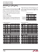
Multiplexer (MUX) Address
The bits of the input word following the START bit assign
the MUX configuration for the requested conversion. For
a given channel selection, the converter will measure the
voltage between the two channels indicated by the + and
– signs in the selected row of the following tables. In
single-ended mode, all input channels are measured with
respect to GND on the LTC1091 and COM on the
LTC1093/LTC1094.
SINGLE-ENDED
MUX MODE
MUX ADDRESS CHANNEL # GND
DIFFERENTIAL
MUX MODE
SGL/
DIFF
1
1
0
0
ODD/
SIGN
0
1
0
1
0
+
+
–
1
+
–
+
–
–
1091-4 AI08
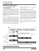
LTC1091 Channel Selection
MUX ADDRESS
SELECT
DIFFERENTIAL CHANNEL SELECTION
SGL/
DIFF
0
0
0
0
0
0
0
0
ODD/
SIGN
0
0
0
0
1
1
1
1
1
0
0
1
1
0
0
1
1
0
0
1
0
1
0
1
0
1
0
+
–
1
–
+
2
+
–
3
–
+
4
+
–
5
–
+
1091-4 AI09
NOT USED
NOT USED
MUX ADDRESS
SELECT
SINGLE-ENDED CHANNEL SELECTION
SGL/
DIFF
1
1
1
1
1
1
1
1
ODD/
SIGN
0
0
0
0
1
1
1
1
1
0
0
1
1
0
0
1
1
0
0
1
0
1
0
1
0
1
0
+
1
+
2
+
3
+
4
+
5
+
COM
–
–
–
–
–
–
NOT USED
NOT USED
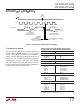
LTC1093 Channel Selection
MUX ADDRESS
SELECT
DIFFERENTIAL CHANNEL SELECTION
SGL/
DIFF
0
0
0
0
0
0
0
0
ODD/
SIGN
0
0
0
0
1
1
1
1
1
0
0
1
1
0
0
1
1
0
0
1
0
1
0
1
0
1
0
+
–
1
–
+
2
+
–
3
–
+
4
+
–
5
–
+
6
+
–
7
–
+
1091-4 AI0
MUX ADDRESS
SELECT
SINGLE-ENDED CHANNEL SELECTION
SGL/
DIFF
1
1
1
1
1
1
1
1
1
0
0
1
1
0
0
1
1
0
0
1
0
1
0
1
0
1
0
+
1
+
2
+
3
+
4
+
5
+
6
+
7
+
COM
–
–
–
–
–
–
–
–
ODD/
SIGN
0
0
0
0
1
1
1
1
LTC1094 Channel Selection