
Datasheet


16
LTC1091/LTC1092
LTC1093/LTC1094
U
S
A
O
PP
L
IC
AT
I
WU
U
I FOR ATIO
3. Accommodating Microprocessors with
Different Word Lengths
The LTC1091/LTC1093/LTC1094 will fill zeros indefinitely
after the transmitted data until CS is brought high. At that
time the D
OUT
line is disabled. This makes interfacing easy
to MPU serial ports with different transfer increments
including 4 bits (e.g., COP400) and 8 bits (e.g., SPI and
MICROWIRE/PLUS
TM
). Any word length can be accommo-
dated by the correct positioning of the start bit in the
LTC1091 input word.
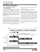
Figure 1 shows examples of LTC1091 input and output
words for 4-bit and 8-bit processors. A complete data
exchange can be implemented with two 4-bit MPU outputs
and three inputs in 4-bit systems and one 8-bit output and
two inputs in 8-bit systems. The resulting data winds up
left justified in the MPU with zeros automatically filled in
the unused low order bits by the LTC1091. In section 5
another example is given using the MC68HC05C4 which
MICROWIRE/PLUS is a trademark of National Semiconductor Corp.
eliminates one 8-bit transfer and positions data right
justified inside the MPU.
4. Operation with D
IN
and D
OUT
Tied Together
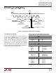
The LTC1091/LTC1093/LTC1094 can be operated with
D
IN
and D
OUT
tied together. This eliminates one of the lines
required to communicate to the MPU. Data is transmitted
in both directions on a single wire. The processor pin
connected to this data line should be configurable as either
an input or an output. The LTC1091, for example, will take
control of the data line and drive it low on the 4th falling
CLK edge after the start bit is received (see Figure 2).
Therefore, the processor port line must be switched to an
input before this happens, to avoid a conflict.
In the next section, an example is made of interfacing
the LTC1091 with D
IN
and D
OUT
tied together to the Intel
8051 MPU.
FILL ZEROS
X = DON’T CARE
1091/2/3/4 F01
CLK
CS
D
OUT
MPU SENDS
2 D
IN
WORDS
4-BIT
TRANSFERS
MPU READS BACK
3 D
OUT
WORDS
START
BIT
D
IN
Hi-Z
START
MSBF
MSBF X
0 0 0 1
• • •
B9 B8 B7 B6 B5 B4 B3 B2 B1 B0
SGL/
DIFF
ODD/
SIGN
SGL/
DIFF
ODD/
SIGN
MSBF X
SGL/
DIFF
ODD/
SIGN
B9 B8 B7 B6 B5 B4 B3 B2 B1 B0 0 0
B9 B8 B7 B6 B5 B4 B3 B2 B1 B0 0 0 0 0 0 0
START
BIT
0 0 0 1
MPU SENDS
1 D
IN
WORD
8-BIT
TRANSFERS
MPU READS BACK
2 D
OUT
WORDS
Figure 1. LTC1091 Input and Output Word Arrangements for 4-Bit and 8-Bit Serial Port Microprocessors