
Datasheet


7
LTC1147-3.3
LTC1147-5/LTC1147L
sn1147 1147fds
MAXIMUM OUTPUT CURRENT (A)
0
R
SENSE
(Ω)
0.15
0.20
4
LTC1147 • F02
0.10
0.05
0
1
2
3
5
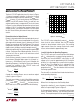
Figure 2. Selecting R
SENSE
L and C
T
Selection for Operating Frequency
The LTC1147 series use a constant off-time architecture
with t
OFF
determined by an external timing capacitor C
T
.
Each time the P-channel MOSFET switch turns on, the
voltage on C
T
is reset to approximately 3.3V. During the
off-time, C
T
is discharged by a current which is propor-
tional to V
OUT
. The voltage on C
T
is analogous to the
current in inductor L, which likewise decays at a rate
proportional to V
OUT
. Thus the inductor value must track
the timing capacitor value.
The value of C
T
is calculated from the desired continuous
mode operating frequency:
C
T
=
1
(1.3)(10
4
)(f)
V
IN
– V
OUT
V
IN
+ V
D
)
)
Where V
D
is the drop across the Schottky diode.
A graph for selecting C
T
versus frequency including the
effects of input voltage is given in Figure 3.
As the operating frequency is increased the gate charge
losses will reduce efficiency (see Efficiency Consider-
ations). The complete expression for operating frequency
The LTC1147 series automatically extend t
OFF
during a
short circuit to allow sufficient time for the inductor
current to decay between switch cycles. The resulting
ripple current causes the average short-circuit current
I
SC(AVG)
to be reduced to approximately I
MAX
.
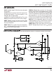
The basic LTC1147 application circuit is shown in Figure
1. External component selection is driven by the load
requirement and begins with the selection of R
SENSE
. Once
R
SENSE
is known, C
T
and L can be chosen. Next, the power
MOSFET and D1 are selected. Finally, C
IN
and C
OUT
are
selected and the loop is compensated. The circuit shown
in Figure 1 can be configured for operation up to an input
voltage of 16V. If the application requires higher input
voltage, then the synchronous switched LTC1149 should
be used. Consult factory for lower minimum input voltage
version.
R
SENSE
Selection for Output Current
R
SENSE
is chosen based on the required output current.
The LTC1147 series current comparator has a thresh-
old range which extends from a minimum of 25mV/
R
SENSE
to a maximum of 150mV/R
SENSE
. The current
comparator threshold sets the peak of the inductor
ripple current, yielding a maximum output current I
MAX
equal to the peak value less half the peak-to-peak ripple
current.
For proper Burst Mode operation, I
RIPPLE(P-P)
must be less than or equal to the minimum current
comparator threshold.
Since efficiency generally increases with ripple current,
the maximum allowable ripple current is assumed, i.e.,
I
RIPPLE(P-P)
= 25mV/R
SENSE
(see C
T
and L Selection for
Operating Frequency). Solving for R
SENSE
and allowing
a margin for variations in the LTC1147 series and
external component values yields:
R
SENSE
=
100mV
I
MAX
A graph for selecting R
SENSE
versus maximum output
current is given in Figure 2.
The load current below in which Burst Mode operation
commences, I
BURST
and the peak short-circuit current
I
SC(PK)
, both track I
MAX
. Once R
SENSE
has been chosen,
I
BURST
and I
SC(PK)
can be predicted from the following:
I
BURST
≈
15mV
R
SENSE
I
SC(PK)
=
150mV
R
SENSE
APPLICATIO S I FOR ATIO
WUU
U