
Datasheet


LTC1196/LTC1198
4
119698fb
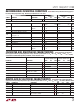
DIGITAL AND DC ELECTRICAL CHARACTERISTICS
The l denotes the specifi cations which
apply over the full operating temperature range, otherwise specifi cations are at T
A
= 25°C. V
CC
= 5V, V
REF
= 5V, unless otherwise noted.
SYMBOL PARAMETER CONDITIONS MIN TYP MAX UNITS
V
OL
Low Level Output Voltage V
CC
= 4.75V, I
O
= 1.6mA
l
0.4 V
I
OZ
Hi-Z Output Leakage CS = HIGH
l
±3 μA
I
SOURCE
Output Source Current V
OUT
= 0V –25 mA
I
SINK
Output Sink Current V
OUT
= V
CC
45 mA
I
REF
Reference Current, LTC1196 CS = V
CC
f
SMPL
= f
SMPL(MAX)
l
l
0.001
0.5
3
1
μA
mA
I
CC
Supply Current CS = V
CC
, LTC1198 (Shutdown)
CS = V
CC
, LTC1196
f
SMPL
= f
SMPL(MAX)
, LTC1196/LTC1198
l
l
l
0.001
7
11
3
15
20
μA
mA
mA
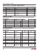
DYNAMIC ACCURACY
The l denotes the specifi cations which apply over the full operating temperature range,
otherwise specifi cations are at T
A
= 25°C. V
CC
= 5V, V
REF
= 5V, f
CLK
= f
CLK(MAX)
as defi ned in Recommended Operating Conditions,
unless otherwise noted.
SYMBOL PARAMETER CONDITIONS MIN
LTC1196
TYP MAX MIN
LTC1198
TYP MAX UNITS
S/(N + D) Signal-to-Noise Plus Distortion 500kHz/1MHz Input Signal 47/45 47/45 dB
THD Total Harmonic Distortion 500kHz/1MHz Input Signal 49/47 49/47 dB
Peak Harmonic or Spurious Noise 500kHz/1MHz Input Signal 55/48 55/48 dB
IMD Intermodulation Distortion f
IN1
= 499.37kHz
f
IN2
= 502.446kHz
51 51 dB
Full-Power Bandwidth 8 8 MHz
Full Linear Bandwidth [S/(N + D) > 44dB 1 1 MHz
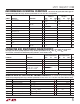
AC CHARACTERISTICS
The l denotes the specifi cations which apply over the full operating temperature range,
otherwise specifi cations are at T
A
= 25°C. V
CC
= 5V, V
REF
= 5V, f
CLK
= f
CLK(MAX)
as defi ned in Recommended Operating Conditions,
unless otherwise noted.
SYMBOL PARAMETER CONDITIONS MIN
LTC1196-1
LTC1198-1
TYP MAX MIN
LTC1196-2
LTC1198-2
TYP MAX UNITS
t
CONV
Conversion Time (See Figures 1, 2)
l
600
710
710
900
ns
ns
f
SMPL(MAX)
Maximum Sampling Frequency LTC1196
LTC1196
LTC1198
LTC1198
l
l
1.20
1.00
0.90
0.75
1.00
0.80
0.75
0.60
MHz
MHz
MHz
MHz
t
dDO
Delay Time, CLK↑ to D
OUT
Data Valid
C
LOAD
= 20pF
l
55 64
73
68 78
94
ns
ns
t
DIS
Delay Time CS↑ to D
OUT
Hi-Z
l
70 120 88 150 ns
t
en
Delay Time, CLK↓ to D
OUT
Enabled
C
LOAD
= 20pF
l
30 50 43 63 ns
t
hDO
Time Output Data Remains Valid After
CLK↑
C
LOAD
= 20pF
l
30 45 30 55 ns
t
f
D
OUT
Fall Time C
LOAD
= 20pF
l
515 1020ns
t
r
D
OUT
Rise C
LOAD
= 20pF
l
515 1020ns
C
IN
Input Capacitance Analog Input On Channel
Analog Input Off Channel
Digital Input
30
5
5
30
5
5
pF
pF
pF