
Datasheet


7
LTC1232
sn1232 1232fas
soon as the reset outputs are inactive. When a high-to-low
transition occurs at the ST pin prior to time-out, the
watchdog time is reset and begins to time-out again. To
ensure the watchdog time does not time-out, a high-to low
transition on the ST pin must occur at or less than the
minimum time-out period. If the input to the ST pin
remains either high or low, reset pulses will be issued for
every time-out period selected by the TD pin. The watch-
dog timer is disabled when V
CC
falls below the V
CC
trip
point.
APPLICATIO S I FOR ATIO
WUUU
Figure 2. Watchdog Time-Out Period and Reset Active Time
condition is satisfied, the reset pulse generator forces the
reset outputs to active states. The reset signals will remain
active for a minimum of 250ms from the moment the
push-button reset input is released from logic low level
(see Timing Diagram).
Watchdog Timer
The LTC1232 provides a watchdog timer function to
monitor the activity of the microprocessor. If the micro-
processor does not stimulate the strobe input, ST, within
a selected time-out period, the reset outputs are forced to
active states for a minimum of 250ms. The time-out period
is selected by the Time-Out Delay input, TD, to be 150ms
with TD connected to GND, 600ms with TD left floating,
and 1.2 seconds with TD connected to V
CC
. The 1.2 second
time-out period is adequate for many systems to serve the
watchdog timer immediately after a reset. Figure 2 shows
the timing diagram of watchdog time-out period and reset
active time. The watchdog time-out period is restarted as
U
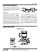
PACKAGE DESCRIPTIO
Information furnished by Linear Technology Corporation is believed to be accurate and reliable.
However, no responsibility is assumed for its use. Linear Technology Corporation makes no represen-
tation that the interconnection of its circuits as described herein will not infringe on existing patent rights.
t
1
= RESET ACTIVE TIME
t
2
= WATCHDOG TIME-OUT PERIOD
t
1
t
2
V
CC
= 5V
LTC1232 • TA04
RST
ST
t
2
t
1
t
1
N8 Package
8-Lead PDIP (Narrow .300 Inch)
(Reference LTC DWG # 05-08-1510)
N8 0502
.100
(2.54)
BSC
.065
(1.651)
TYP
.045 – .065
(1.143 – 1.651)
.130 ± .005
(3.302 ± 0.127)
.020
(0.508)
MIN
.018 ± .003
(0.457 ± 0.076)
.125
(3.175)
MIN
12
3
4
87 6
5
.255 ± .015*
(6.477 ± 0.381)
.400*
(10.160)
MAX
.009 – .015
(0.229 – 0.381)
.300 – .325
(7.620 – 8.255)
.325
+.035
–.015
+0.889
–0.381
8.255
()
NOTE:
1. DIMENSIONS ARE
INCHES
MILLIMETERS
*THESE DIMENSIONS DO NOT INCLUDE MOLD FLASH OR PROTRUSIONS.
MOLD FLASH OR PROTRUSIONS SHALL NOT EXCEED .010 INCH (0.254mm)