
Datasheet


12
LTC1274/LTC1277
APPLICATIONS INFORMATION
WUU
U
Full-Power and Full-Linear Bandwidth
The full-power bandwidth is that input frequency at which
the amplitude of the reconstructed fundamental is re-
duced by 3dB for a full-scale input signal.
The full-linear bandwidth is the input frequency at which
the S/(N + D) has dropped to 68dB (11 effective bits). The
LTC1274/LTC1277 have been designed to optimize input
bandwidth, allowing ADCs to undersample input signals
with frequencies above the converter’s Nyquist frequency.
The noise floor stays very low at high frequencies;
S/(N + D) becomes dominated by distortion at frequencies
far beyond Nyquist.
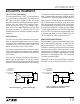
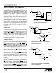
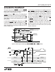
Driving the Analog Input
The analog input of the LTC1274/LTC1277 is easy to
drive. It draws only one small current spike while charg-
ing the sample-and-hold capacitor at the end of conver-
sion. During conversion the analog input draws only a
small leakage current. The only requirement is that the
amplifier driving the analog input must settle after the
small current spike before the next conversion starts.
Any op amp that settles in 2µs to small current transients
will allow maximum speed operation. If slower op amps
are used, more settling time can be provided by increasing
the time between conversions. Suitable devices capable of
driving the ADC A
IN
input include the LT
®
1006, LT1007,
LT1220, LT1223 and LT1224 op amps.
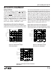
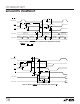
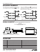
quency is shown in Figure 4. The ADCs have good distor-
tion performance up to the Nyquist frequency and beyond.
Intermodulation Distortion
If the ADC input signal consists of more than one spectral
component, the ADC transfer function nonlinearity can pro-
duce intermodulation distortion (IMD) in addition to THD.
IMD is the change in one sinusoidal input caused by the
presence of another sinusoidal input at a different frequency.
If two pure sine waves of frequencies fa and fb are applied
to the ADC input, nonlinearities in the ADC transfer func-
tion can create distortion products at sum and difference
frequencies of mfa ± nfb, where m and n = 0, 1, 2, 3, etc.
For example, the 2nd order IMD terms include (fa + fb) and
(fa – fb) while the 3rd order IMD terms include (2fa + fb),
(2fa – fb), (fa + 2fb) and (fa – 2fb). If the two input sine
waves are equal in magnitude, the value (in decibels) of the
2nd order IMD products can be expressed by the following
formula:
IMD (fa ± fb) = 20log
Amplitude at (fa ± fb)
Amplitude at fa
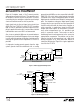
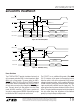
Figure 5 shows the IMD performance at a 97kHz input.
Peak Harmonic or Spurious Noise
The peak harmonic or spurious noise is the largest spec-
tral component excluding the input signal and DC. This
value is expressed in decibels relative to the RMS value of
a full scale input signal.
Figure 4. Distortion vs Input Frequency
Figure 5. Intermodulation Distortion
FREQUENCY (Hz)
0
AMPLITUDE (dB)
0
–20
–40
–60
–80
–100
–120
10k 20k 30k 40k
LTC1274/77 • F05
50k
2fb – fa
fb
fa
fb – fa
2fb
2fa – fb
2fa
3fb
2fb + fa
2fa + fb
fa + fb
3fa
f
SAMPLE
= 100kHz
fa = 96.948kHz
fb = 97.681kHz
THD
INPUT FREQUENCY (Hz)
10k
DISTORTION (dB)
0
–20
–40
–60
–80
–100
–120
100k 1M 2M
LTC1274/77 • F04
3RD HARMONIC
2ND HARMONIC
f
SAMPLE
= 100kHz