
Datasheet


12
LTC1334
U
S
A
O
PP
L
IC
AT
I
WU
U
I FOR ATIO
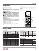
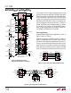
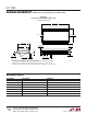
Figure 12. Multiprotocol Interface
with Optional, Switchable Terminations
326
25
RX OUT
24
RX OUT
22
DR IN
8
SEL1
23
21
DR IN/ENABLE
LB
V
CC
5V
LTC1334 • F12
LTC1334
28
C2C1
2
1
27
V
EE
V
DD
4
INPUT A
K1A
K1B
120Ω
5
INPUT B
6
OUTPUT A
7
OUTPUT B
13
INPUT A
12
INPUT B
11
OUTPUT A
10
14
OUTPUT B
PORT 1
INTERFACE
20
16
ON/OFF
RX OUT
17
RX OUT
19
DR IN
9
SEL2
18
15
DR IN/ENABLE
PORT 2
INTERFACE
AROMAT CORP (800) 276-6289
ZETEX (516) 543-7100
*
**
0.1µF
0.1µF 0.1µF
0.1µF0.1µF
120Ω
K2A
120Ω
K2B
120Ω
TERM1
360k
FMMT619**
K1*
TX2A-5V
7.5k
TERM2
360k
FMMT619**
K2*
TX2A-5V
7.5k
5V
5V
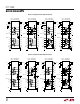
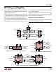
Figure 13. Typical Connection for RS232/EIA562 Interface
1/2 LTC1334 1/2 LTC1334
LTC1334 • F13
19
18
17
16
9
DR IN
DR IN
RX OUT
RX OUT
4
5
6
7
11
10
13
12
24
25
22
23
8
RX OUT
RX OUT
DR IN
DR IN
RS232/
EIA562
INTERFACE
LINES
Each receiver in the LTC1334 is designed to present one
unit load (5kΩ nominal for RS232 and 12kΩ minimum for
RS485) to the cable. Some RS485 and RS422 applications
call for terminations, but these are only necessary at two
nodes in the system and they must be disconnected when
operating in the RS232 mode. A relay is the simplest, low-
est cost method of switching terminations. In Figure 12
TERM1 and TERM2 select 120Ω terminations as needed.
If terminations are needed in all RS485/RS422 applica-
tions, no extra control signals are required; simply con-
nect TERM1 and TERM2 to SEL1 and SEL2.
Typical Applications
A typical RS232/EIA562 interface application is shown in
Figure 13 with the LTC1334.
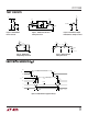
A typical connection for a RS485 transceiver is shown in
Figure 14. A twisted pair of wires connects up to 32 drivers
and receivers for half duplex multipoint data transmission.
The wires must be terminated at both ends with resistors
equal to the wire’s characteristic impedance. An optional
shield around the twisted pair helps to reduce unwanted
noise and should be connected to ground at only one end.
Figure 14. Typical Connection for RS485 Interface
5V
4
1/2 LTC1334
1/2
LTC1334
1/2 LTC1334
LTC1334 F14
RX OUT
DR ENABLE
DR IN
5V
120Ω
5
6
7
24
23
22
8
13
12
11
10
9
RX OUT
18
5V
DR ENABLE
76 54
22
DR IN RX OUT
DR ENABLE
23 24 8
17
DR IN
19
120Ω