
Datasheet


3
LTC1337
1337fa
DC ELECTRICAL CHARACTERISTICS
AC CHARACTERISTICS
The ● denotes specifications which apply over the full operating
temperature range. V
CC
= 5V, C1 = C2 = C3 = C4 = 0.1µF, unless otherwise noted.
The ● denotes specifications which apply over the full operating temperature range.
V
CC
= 5V, C1 = C2 = C3 = C4 = 0.1µF, unless otherwise noted.
PARAMETER CONDITIONS MIN TYP MAX UNITS
Power Supply Generator
V
+
Output Voltage I
OUT
= 0mA 8.0 V
I
OUT
= 12mA 7.5 V
V
–
Output Voltage I
OUT
= 0mA –8.0 V
I
OUT
= 12mA –6.5 V
Supply Rise Time Shutdown to Turn-On 0.2 ms
Power Supply
V
CC
Supply Current No Load (Note 2) ● 0.3 0.5 mA
Supply Leakage Current (V
CC
)Shutdown (Note 3) ● 110 µA
On/Off Threshold Low ● 1.4 0.8 V
On/Off Threshold High ● 2.0 1.4 V
TYPICAL PERFOR A CE CHARACTERISTICS
UW
TEMPERATURE (°C)
0
THRESHOLD VOLTAGE (V)
60
2.0
1.9
1.8
1.7
1.6
1.5
1.4
1.3
1.2
1.1
1337 G02
20 7010
30
40
50
INPUT HIGH
INPUT LOW
Driver Output Voltage Receiver Input Thresholds Supply Current vs Data Rate
DATA RATE (k BAUD)
0
SUPPLY CURRENT (mA)
150
45
40
35
30
25
20
15
10
5
0
1337 G03
50 17525
75
100
125
V
CC
= 5V
R
L
= 3k
C
L
= 2500pF
3 DRIVERS ACTIVE
TEMPERATURE (°C)
0
DRIVER OUTPUT VOLTAGE (V)
60
10
8
6
4
2
0
–2
–4
–6
–8
1337 G01
20 7010
30
40
50
V
CC
= 5V
OUTPUT HIGH
V
CC
= 4.5V
R
L
= 3k
V
CC
= 5V
V
CC
= 4.5V
OUTPUT LOW
Note 1: Absolute Maximum Ratings are those values beyond which the life
of the device may be impaired.
Note 2: Supply current is measured with driver and receiver outputs
unloaded and driver inputs tied high.
Note 3: Supply current and leakage measurements in Shutdown are
performed with V
ON
= 0V.
PARAMETER CONDITIONS MIN TYP MAX UNITS
Slew Rate R
L
= 3k, C
L
= 51pF 8 30 V/µs
R
L
= 3k, C
L
= 2500pF 2 4 V/µs
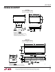
Driver Propagation Delay t
HLD
(Figure 1) ● 23 µs
(TTL to RS232) t
LHD
(Figure 1) ● 23 µs
Receiver Propagation Delay t
HLR
(Figure 2) ● 0.3 0.6 µs
(RS232 to TTL) t
LHR
(Figure 2) ● 0.2 0.6 µs