
Datasheet


11
LTC1343
APPLICATIONS INFORMATION
WUU
U
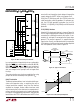
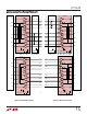
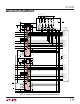
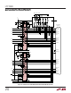
Figure 12: Mode Selection by the Controller
has a unique data latch signal which acts as a write enable.
When the LATCH pin is low the buffers on the M0, M1, M2,
CTRL/CLK, DCE/DTE, LB and EC pins are transparent.
When the LATCH pin is pulled high the buffers latch the
data and changes on the input pins will no longer affect
the chip.
The mode selection may also be accomplished by using
jumpers to connect the mode pins to ground or V
CC
.
Cable Termination
Traditional implementations have included switching re-
sistors with expensive relays, or requiring the user to
change termination modules every time the interface
standard has changed. Custom cables have been used
with the termination in the cable head, or separate termi-
nations are built on the board and a custom cable routes
the signals to the appropriate termination. Switching the
terminations with FETs is difficult because the FETs must
remain off even though the signal voltage is beyond the
supply voltage for the FET drivers or the power is off.
Using the LTC1344 along with the LTC1343 solves the
cable termination switching problem. Via software con-
trol, the LTC1344 provides termination for the V.10
(RS423), V.11 (RS422), V.28 (RS232) and V.35 electrical
protocols.
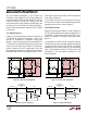
V.10 (RS423) Interface
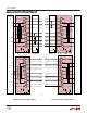
A typical V.10 unbalanced interface is shown in Figure 13.
A V.10 single-ended generator output A with ground C is
connected to a differential receiver with inputs A' con-
nected to A, and input B' connected to the signal return
ground C. The receiver’s ground C' is separate from the
signal return. Usually, no cable termination is required for
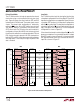
V.10 interfaces, but the receiver inputs must be compliant
with the impedance curve shown in Figure 14.
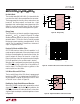
Figure 14. V.10 Receiver Input Impedance
Figure 13. Typical V.10 Interface
1343 F12
CONTROLLER
PORT #3
M0
M1
M2
DCE/DTE
LATCH 1
LATCH 2
LATCH 3
M0
M1
M2
DCE/DTE
LATCH
PORT #2
M0
M1
M2
DCE/DTE
LATCH
PORT #1
M0
M1
M2
DCE/DTE
LATCH
CONNECTOR #1CONNECTOR #2CONNECTOR #3
AA
'
CB
'
C
'
GENERATOR
BALANCED
INTERCONNECTING
CABLE
LOAD
CABLE
TERMINATION
RECEIVER
1343 F13
I
Z
V
Z
–10V
–3.25mA
3.25mA
–3V
3V 10V
1343 F14