
Datasheet


12
LTC1343
APPLICATIONS INFORMATION
WUU
U
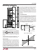
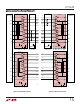
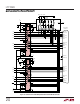
The V.10 receiver configuration in the LTC1343 and
LTC1344 is shown in Figure 15. In V.10 mode switches S1
and S2 inside the LTC1344 and S3 inside the LTC1343 are
turned off. Switch S4 inside the LTC1343 shorts the
noninverting receiver input to ground so the B input at the
connector can be left floating. The cable termination is
then the 30k input impedance to ground of the LTC1343
V.10 receiver.
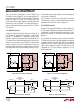
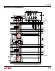
V.11 (RS422) Interface
A typical V.11 balanced interface is shown in Figure 16. A
V.11 differential generator with outputs A and B with
ground C is connected to a differential receiver with
ground C', inputs A' connected to A, B' connected to B. The
V.11 interface has a differential termination at the receiver
end that has a minimum value of 100Ω. The termination
resistor is optional in the V.11 specification, but for the
high speed clock and data lines, the termination is required
to prevent reflections from corrupting the data. The re-
ceiver inputs must also be compliant with the impedance
curve shown in Figure 14.
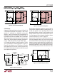
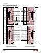
In V.11 mode, all switches are off except S1 inside the
LTC1344 which connects a 103Ω differential termination
impedance to the cable as shown in Figure 17.
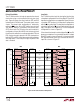
V.28 (RS232) Interface
A typical V.28 unbalanced interface is shown in Figure 18.
A. V.28 single-ended generator output A with ground C is
connected to a single-ended receiver with inputs A' con-
nected to A, ground C' connected via the signal return
ground C.
In V.28 mode all switches are off except S3 inside the
LTC1343 which connects a 6k (R8) impedance to ground
in parallel with 20k (R5) plus 10k (R6) for a combined
impedance of 5k as shown in Figure 19. The noninverting
input is disconnected inside the LTC1343 receiver and
connected to a TTL level reference voltage for a 1.4V
receiver trip point.
Figure 17. V.11 Receiver Configuration
Figure 15. V.10 Receiver Configuration
Figure 18. Typical V.28 Interface
Figure 16. Typical V.11 Interface
R3
124Ω
R5
20k
LTC1344
LTC1343
RECEIVER
1343 F15
A
B
A
'
B'
C'
R1
51.5Ω
R8
6k
S1
S2
S3
S4
R2
51.5Ω
R6
10k
R7
10k
GND
R4
20k
AA'
B
C
B'
C'
GENERATOR
BALANCED
INTERCONNECTING
CABLE
LOAD
CABLE
TERMINATION
RECEIVER
100Ω
MIN
1343 F16
R3
124Ω
R5
20k
LTC1344
LTC1343
RECEIVER
1343 F17
A
B
A
'
B'
C'
R1
51.5Ω
R8
6k
S2
S3
S4
R2
51.5Ω
R6
10k
R7
10k
GND
R4
20k
S1
AA
'
CC
'
GENERATOR
BALANCED
INTERCONNECTING
CABLE
LOAD
CABLE
TERMINATION
RECEIVER
1343 F18