
Datasheet


18
LTC1343
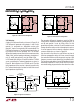
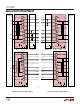
drivers and receivers into a high impedance state. In the
DCE mode, the middle two LTC1343s are enabled and the
top and bottom LTC1343s disabled. With this scheme, any
connector pin can be configured for sending or receiving
signals. Note that only one LTC1344 is required.
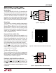
Multiprotocol Interface with Ring-Indicate and a
DB-25 Connector
If the RI signal in RS232 mode is implemented, driver 4
and receiver 1 in the control chip can be tied to connector
Pin 22 in order to implement the RI signal in RS232 mode
and DSR B signal for the other modes. Figure 35 shows the
DTE configuration and Figure 36 the DCE configuration. In
DCE mode, the DCE/DTE pin should be driven with a logic
signal from the controller that goes low only when the
interface is in the RS232 mode. Since the receiver 4 input
impedance is greater than 30kΩ in all modes except
RS232, it can be enabled at all other times and not load
down the line. When driver 1 is disabled, it remains in a
high impedance state and does not load the line.
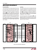
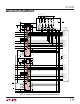
Cable-Selectable Multiprotocol Interface
A cable-selectable multiprotocol DTE/DCE interface is
shown in Figure 37. The control signals LL, RL and TM are
not implemented. The select lines M0, M1 and DCE/DTE
are brought out to the connector. The mode is selected
through the cable by wiring M0 (connector Pin 18), M1
(connector Pin 21) and DCE/DTE (connector Pin 25) to
ground (connector Pin 7) or letting them float. If M0, M1
or DCE/DTE are floating, pull-up resistors R3, R4 and R5
will pull the signals to V
CC
. The select bit M1 is hard wired
to V
CC
. When the cable is pulled out, the interface will go
into the no-cable mode.
Multiprotocol Interface with a µDB-26 Connector
The controller-selectable multiprotocol DTE/DCE inter-
face with a standard µDB-26 connector is shown in Figure
38. The RL, LL and TM signals are implemented and RI is
mapped to Pin 26 on the connector. A cable-selectable
version is shown in Figure 39. The TM and RL signals have
been dropped, but LL is still implemented.
The EC pin has no affect on the configuration when CTRL/
CLK is high except to allow the DCE/DTE pin to become an
enable. When DCE/DTE is low, the driver 1 output is
enabled. The receiver 4 output goes into three-state and
the input presents a 30kΩ load to ground.
When DCE/DTE is high, the driver 1 output goes into three-
state and the receiver 4 output is enabled. The receiver 4
input presents a 30kΩ load to ground in all modes except
when configured for RS232 operation when the input
impedance is 5kΩ to ground.
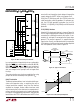
DTE vs DCE Operation
The DCE/DTE pin does not allow a given LTC1343 pin to be
reconfigured as a driver or receiver. The DCE/DTE pin only
selects the loop-back topology and acts as an enable for
the single-ended driver and receiver for control signals.
However, the LTC1343 can be configured for either DTE or
DCE operation in one of three ways: a dedicated DTE or
DCE port with a connector of appropriate gender, a port
with one connector that can be configured for DTE or DCE
operation by rerouting the signals to the LTC1343 using a
dedicated DTE cable or dedicated DCE cable, or a port with
one connector and one cable using four LTC1343s.
A dedicated DTE port using a DB-25 male connector is
shown in Figure 31. The interface mode is selected by logic
outputs from the controller or from jumpers to either V
CC
or GND on the mode select pins. A dedicated DCE port
using a DB-25 female connector is shown in Figure 32.
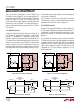
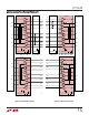
A port with one DB-25 connector that can be configured
for either DTE or DCE operation is shown in Figure 33. The
configuration requires separate cables for proper signal
routing in DTE or DCE operation. For example, in DTE
mode, the TXD signal is routed to connector Pins 2 and 14
via driver 2 in the LTC1343. In DCE mode, driver 2 now
routes the RXD signal to Pins 2 and 14.
A combination DTE/DCE port that doesn’t require separate
DCE/DTE cables is shown in Figure 34. In DTE mode, the
top and bottom LTC1343s are enabled and the middle two
are placed in the no-cable mode, which forces all of the
APPLICATIONS INFORMATION
WUU
U