
Datasheet

6
LTC1343
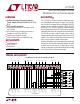
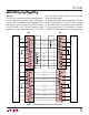
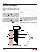
PIN FUNCTIONS
UUU
respective input buffers. The data latch allows the logic
lines to be shared between multiple I/O ports.
LB (Pin 23): TTL Level Loop-Back Select Input. When low
the chip enters the loop-back configuration and is config-
ured for normal operation when LB is high. The data on LB
is latched when LATCH is high.
EC (Pin 24): TTL Level Echoed Clock Select Input. When
low the part enters the echoed clock configuration and is
configured for normal operation when EC is high. The data
on EC is latched when LATCH is high.
423 SET (Pin 25): Analog Input Pin for the RS423 Driver
Output Rise and Fall Time Set Resistor. Connect the
resistor from the pin to ground.
R4 A (Pin 26): Receiver 4 Inverting Input.
R3 B (Pin 27): Receiver 3 Noninverting Input.
R3 A (Pin 28): Receiver 3 Inverting Input.
R2 B (Pin 29): Receiver 2 Noninverting Input.
R2 A (Pin 30): Receiver 2 Inverting Input.
R1 B (Pin 31): Receiver 1 Noninverting Input.
R1 A (Pin 32): Receiver 1 Inverting Input.
D4 B (Pin 33): Driver 4 Noninverting Output.
D4 A (Pin 34): Driver 4 Inverting Output.
D3 B (Pin 35): Driver 3 Noninverting Output.
D3 A (Pin 36): Driver 3 Inverting Output.
D2 B (Pin 37): Driver 2 Noninverting Output.
D2 A (Pin 38): Driver 2 Inverting Output.
D1 A (Pin 39): Driver 1 Inverting Output.
GND (Pin 40): Signal Ground. Connect to PGND (Pin 41).
PGND (Pin 41): Charge Pump Power Ground. Connect to
the GND (Pin 40).
V
EE
(Pin 42): Generated Negative Supply Voltage. Connect
a 3.3µF capacitor to ground.
C2
–
(Pin 43): Capacitor C2 Negative Terminal. Connect a
1µF capacitor between C2
+
and C2
–
.
C2
+
(Pin 44): Capacitor C2 Positive Terminal. Connect a
1µF capacitor between C2
+
and C2
–
.
V
CC
(Pin 8): Positive Supply for the Transceivers. 4.75V ≤
V
CC
≤ 5.25V. Tie to PWRV
CC
(Pin 3).
D4 (Pin 9): TTL Level Driver 4 Input.
D4EN (Pin 10): TTL Level Enable Input for Driver 4. When
high, driver 4 outputs are enabled. When low, driver 4
outputs are forced into a high impedance state. D4EN is
not affected by the LATCH pin.
INVERT (Pin 11): TTL Level Signal Invert Input. When
high, an extra inverter will be added to the driver 4 and
receiver 1 signal path. The data stream will change polar-
ity, i.e., a 1 becomes 0 and a 0 becomes a 1. When the pin
is low the data flows through with no polarity change.
INVERT is not affected by the LATCH pin.
R1EN (Pin 12): Logic Level Enable Input for Receiver 1.
When low, receiver 1 output is enabled. When high,
receiver 1 output is forced into a high impedance state.
R1O (Pin 13): CMOS Level Receiver 1 Output.
R2O (Pin 14): CMOS Level Receiver 2 Output.
R3O (Pin 15): CMOS Level Receiver 3 Output.
R4O (Pin 16): CMOS Level Receiver 4 Output.
M0 (Pin 17): TTL Level Mode Select Input 0. The data on
M0 is latched when LATCH is high.
M1 (Pin 18): TTL Level Mode Select Input 1. The data on
M1 is latched when LATCH is high.
M2 (Pin 19): TTL Level Mode Select Input 2. The data on
M2 is latched when LATCH is high.
CTRL/CLK (Pin 20): TTL Level Mode Select Input. When
the pin is low the chip will be configured for clock and data
signals. When the pin is high the chip will be configured for
control signals. The data on CTRL/CLK is latched when
LATCH is high.
DCE/DTE (Pin 21): TTL Level Mode Select Input. When
high, the DCE mode is selected. When low the DTE mode
is selected. The data on DCE/DTE is latched when LATCH
is high.
LATCH (Pin 22): TTL Level Logic Signal Latch Input. When
low the input buffers on M0, M1, M2, CTRL/CLK, DCE/
DTE, LB and EC are transparent. When LATCH is pulled
high the data on the logic pins is latched into their