
Datasheet


8
LTC1344A
APPLICATIONS INFORMATION
WUU
U
A
CABLE
TERMINATION
LOADGENERATOR
BALANCED
INTERCONNECTING
CABLE
RECEIVER
A
'
50Ω
50Ω
125Ω
B
C
B
'
C
'
1344 F10
125Ω
50Ω
50Ω
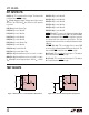
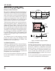
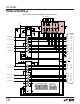
Figure 10. Typical V.35 Interface
Z
Z
Z
S1
ON
S2
ON
124Ω
LTC1344A
V.35
RECEIVER
A
B
C
1344 F11
51.5Ω
51.5Ω
I
Z
–3V
3V 12V
–7V
–0.8mA
1mA
V
Z
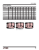
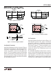
Figure 11. V.35 Receiver Using the LTC1344A
if the receiver input impedance is on the low side. All of
Linear Technology’s V.35 receivers meet the RS485 input
impedance specification as shown in Figure 11, which
insures compliance with the V.35 specification when used
with the LTC1344A.
S1
ON
S2
ON
124Ω
LTC1344A
V.35
DRIVER
A
B
C
1344 F12
51.5Ω
51.5Ω
C1
100pF
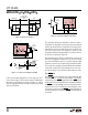
Figure 12. V.35 Driver Using the LTC1344A
The generator differential impedance must be 50Ω to
150Ω and the impedance between shorted terminals A
and B to ground C must be 150Ω ±15Ω. For the generator
termination, switches S1 and S2 are both on and the top
side of the center resistor is brought out to a pin so it can
be bypassed with an external capacitor to reduce common
mode noise as shown in Figure 12.
Any mismatch in the driver rise and fall times or skew in
the driver propagation delays will force current through
the center termination resistor to ground causing a high
frequency common mode spike on the A and B terminals.
The common mode spike can cause EMI problems that are
reduced by capacitor C1 which shunts much of the com-
mon mode energy to ground rather than down the cable.
The LATCH Pin
The LATCH pin (21) allows the select lines (M0, M1, M2
and DCE/DTE) to be shared with multiple LTC1344As,
each with its own LATCH signal. When the LATCH pin is
held low the select line input buffers are transparent. When
the LATCH pin is pulled high, the select line input buffers
latch the state of the Select pins so that changes on the
select lines are ignored until LATCH is pulled low again. If
the latch feature is not used, the LATCH pin should be tied
to ground.