
Datasheet


7
LTC1344
APPLICATIONS INFORMATION
WUU
U
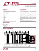
Figure 6. Typical V.11 Interface
Z
Z
Z
S1
ON
S2
OFF
124Ω
LTC1344
V.11
RECEIVER
A
B
C
1344 F07
51.5Ω
51.5Ω
I
Z
–3V
3V 10V
–10V
–3.25mA
3.25mA
V
Z
Figure 7. V.11 Interface Using the LTC1344
V.28 (RS232) Termination
A typical V.28 unbalanced interface is shown in Figure 8.
A V.28 single-ended generator output A with ground C is
connected to a single-ended receiver with inputs A' con-
nected to A, ground C' connected via the signal return
ground to C. The V.28 standard requires a 5k terminating
resistor to ground which is included in almost all compli-
ant receivers as shown in Figure 9. Because the termina-
tion is included in the receiver, both switches S1 and S2 in
the LTC1344 are turned off.
A
CABLE
TERMINATION
LOADGENERATOR
BALANCED
INTERCONNECTING
CABLE
RECEIVER
A
'
CC'
1344 F08
Figure 8. Typical V.28 Interface
S1
OFF
S2
OFF
124Ω
LTC1344
V.28
RECEIVER
A
B
C
1344 F09
51.5Ω
51.5Ω
5k
Figure 9. V.28 Interface Using the LTC1344
V.35 Termination
A typical V.35 balanced interface is shown in Figure 10. A
V.35 differential generator with outputs A and B with
ground C is connected to a differential receiver with
ground C', inputs A' connected to A, B' connected to B. The
V.35 interface requires a T-network termination at the
receiver end and the generator end. In V.35 mode both
switches S1 and S2 in the LTC1344 are turned on as
shown in Figure 11.
The differential impedance measured at the connector
must be 100Ω ±10Ω and the impedance between shorted
terminals A' and B' to ground C' must be 150Ω ±15Ω. The
input impedance of the V.35 receiver is connected in
parallel with the T-network inside the LTC1344, which can
cause the overall impedance to fail the specification on the
A
CABLE
TERMINATION
LOADGENERATOR
BALANCED
INTERCONNECTING
CABLE
RECEIVER
A
'
BB
'
C
'
C
100Ω
MIN
1344 F06