
Datasheet

6
LTC1344
APPLICATIONS INFORMATION
WUU
U
Multiprotocol Cable Termination
One of the most difficult problems facing the designer of
a multiprotocol serial interface is how to allow the trans-
mitters and receivers for different electrical standards to
share connector pins. In some cases the transmitters and
receivers for each interface standard can be simply tied
together and the appropriate circuitry enabled. But the
biggest problem still remains: how to switch the various
cable terminations required by the different standards.
Traditional implementations have included switching re-
sistors with expensive relays or requiring the user to
change termination modules every time the interface
standard has changed. Custom cables have been used
with the termination in the cable head or separate termina-
tions are built on the board, and a custom cable routes the
signals to the appropriate termination. Switching the
terminations using FETs is difficult because the FETs must
remain off even though the signal voltage is beyond the
supply voltage for the FET drivers or the power is off.
The LTC1344 solves the cable termination switching prob-
lem via software control. The LTC1344 provides termina-
tion for the V.10 (RS423), V.11 (RS422), V.28 (RS232)
and V.35 electrical protocols.
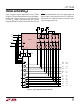
V.10 (RS423) Termination
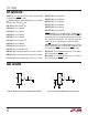
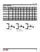
A typical V.10 unbalanced interface is shown in Figure 4.
A V.10 single-ended generator output A with ground C is
connected to a differential receiver with inputs A' con-
nected to A and input B' connected to the signal return
ground C. The receiver’s ground C' is separate from the
signal return. Usually no cable termination is required for
V.10 interfaces but the receiver inputs must be compliant
with the impedance curve shown in Figure 5.
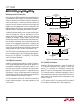
In V.10 mode, both switches S1 and S2 are turned off so
the only cable termination is the input impedance of the
V.10 receiver.
A
CABLE
TERMINATION
LOADGENERATOR
BALANCED
INTERCONNECTING
CABLE
RECEIVER
A
'
C
B
'
C
'
1344 F04
Figure 4. Typical V.10 Interface
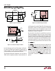
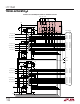
V.11 (RS422) Termination
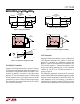
A typical V.11 balanced interface is shown in Figure 6. A
V.11 differential generator with outputs A and B with
ground C is connected to a differential receiver with
ground C', inputs A' connected to A, B' connected to B. The
V.11 interface requires a different termination at the re-
ceiver end that has a minimum value of 100Ω. The receiver
inputs must also be compliant with the impedance curve
shown in Figure 7.
In V.11 mode, switch S1 is turned on and S2 is turned off
so the cable is terminated with a 103Ω impedance.
Figure 5. V.10 Interface Using the LTC1344
Z
Z
Z
S2
OFF
124Ω
LTC1344
V.10
RECEIVER
A
B
C
1344 F05
51.5Ω
51.5Ω
I
Z
–3V
3V 10V
–10V
–3.25mA
3.25mA
V
Z
S1
OFF