
Datasheet


3
LTC1383
1383fa
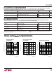
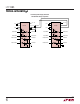
DC ELECTRICAL CHARACTERISTICS
AC CHARACTERISTICS
Note 1: Absolute Maximum Ratings are those values beyond which the life
of the device may be impaired.
PARAMETER CONDITIONS MIN TYP MAX UNITS
Slew Rate R
L
= 3k, C
L
= 51pF 8 30 V/µs
R
L
= 3k, C
L
= 2500pF 3 5 V/µs
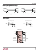
Driver Propagation Delay t
HLD
(Figure 1) ● 2 3.5 µs
(TTL to RS232) t
LHD
(Figure 1) ● 2 3.5 µs
Receiver Propagation Delay t
HLR
(Figure 2) ● 0.3 0.8 µs
(RS232 to TTL) t
LHR
(Figure 2) ● 0.3 0.8 µs
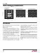
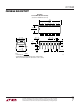
TYPICAL PERFOR A CE CHARACTERISTICS
UW
TEMPERATURE (°C)
0
–8
DRIVER OUTPUT VOLTAGE (V)
–6
–2
0
2
40
10
LTC1383 • TPC01
–4
20
10
50 60
30 70
4
6
8
R
L
= 3k
V
CC
= 5V
V
CC
= 4.5V
OUTPUT HIGH
V
CC
= 4.5V
V
CC
= 5V
OUTPUT LOW
Driver Output Voltage
vs Temperature
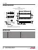
DATA RATE (kBAUD)
0
0
SUPPLY CURRENT (mA)
5
15
20
25
100
45
LTC1383 • TPC03
10
50
25
125
75 150 175
30
35
40
V
CC
= 5V
R
L
= 3k
C
L
= 2500pF
2 DRIVERS ACTIVE
TEMPERATURE (˚C)
0
THRESHOLD VOLTAGE (V)
1.8
2.0
2.2
30 50
V
TH
V
TL
LTC1383 • TPC02
1.6
1.4
10 20
40 60 70
1.2
1.0
Receiver Input Thresholds
vs Temperature
Supply Current vs Data Rate
The
● denotes specifications which apply over the full operating
temperature range, otherwise specifications are at T
A
= 25°C. V
CC
= 5V, C1 = C2 = C3 = C4 = 0.1µF, unless noted.
The ● denotes specifications which apply over the full operating temperature range,
otherwise specifications are at T
A
= 25°C. V
CC
= 5V, C1 = C2 = C3 = C4 = 0.1µF, unless noted.
Note 2: Supply current is measured with driver and receiver outputs
unloaded.
PARAMETER CONDITIONS MIN TYP MAX UNITS
Power Supply
V
CC
Supply Current No Load (Note 2), 0°C to 70°C ● 0.22 0.5 mA
No Load (Note 2), – 40°C to 85°C ● 0.35 1.0 mA
Digital Input Threshold Low ● 1.4 0.8 V
Digital Input Threshold High ● 2.0 1.4 V