
Datasheet


4
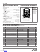
LTC1387
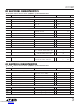
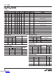
AC ELECTRICAL CHARACTERISTICS
T
A
= 25°C, V
CC
= 5V, C1 = C2 = C3 = C4 = 0.1µF (Notes 2, 3), unless otherwise noted.
The ● denotes specifications which apply over the full operating
temperature range.
Note 1: Absolute Maximum Ratings are those values beyond which the life
of the device may be impaired.
Note 2: All currents into device pins are positive; all currents out of device
pins are negative. All voltages are referenced to device ground unless
otherwise specified.
Note 3: All typicals are given at V
CC
= 5V, C1 = C2 = C3 = C4 = 0.1µF
and T
A
= 25°C.
Note 4: Short-circuit current for RS485 driver output low state folds back
above V
CC
. Peak current occurs around V
O
= 3V.
Note 5: SLEW includes an internal pull-up in RS485 mode.
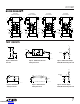
PIN FUNCTIONS
UUU
C1
+
(Pin 1): Commutating Capacitor C1 Positive Terminal.
Requires an external 0.1µF capacitor between Pins 1 and 2.
C1
–
(Pin 2): Commutating Capacitor C1 Negative Terminal.
V
DD
(Pin 3): Charge Pump Positive Supply Output.
Requires an external 0.1µF capacitor to ground.
A (Pin 4): Receiver Input A. Inverting input of RS232
receiver A in RS232 mode; inverting RS485 receiver input
in RS485 mode.
B (Pin 5): Receiver Input B. Inverting input of RS232
receiver B in RS232 mode; noninverting RS485 receiver
input in RS485 mode.
Y (Pin 6): Driver Output Y. Inverting RS232 driver Y output
in RS232 mode; inverting RS485 driver output in RS485
mode.
Z (Pin 7): Driver Output Z. Inverting RS232 driver Z output
in RS232 mode; noninverting RS485 driver output in
RS485 mode.
SYMBOL PARAMETER CONDITIONS MIN TYP MAX UNITS
RS485 Mode (Fast Slew Rate, ON = DXEN = High, 485/232 = High, SLEW = High)
t
ZL
Driver Enable to Output Low Figures 3, 8, C
L
= 100pF, S1 Closed ● 50 90 ns
t
ZH
Driver Enable to Output High Figures 3, 8, C
L
= 100pF, S2 Closed ● 50 90 ns
t
LZ
Driver Disable from Low Figures 3, 8, C
L
= 15pF, S1 Closed ● 50 90 ns
t
HZ
Driver Disable from High Figures 3, 8, C
L
= 15pF, S2 Closed ● 60 90 ns
RS485 Mode (Slow Slew Rate, ON = DXEN = High, 485/232 = High, SLEW = Low)
t
PLH
Driver Input to Output Figures 2, 7, R
L
= 54Ω, C
L
= 100pF ● 100 700 1500 ns
t
PHL
Driver Input to Output Figures 2, 7, R
L
= 54Ω, C
L
= 100pF ● 100 700 1500 ns
t
SKEW
Driver Output to Output Figures 2, 7, R
L
= 54Ω, C
L
= 100pF ● 200 750 ns
t
r
, t
f
Driver Rise or Fall Time Figures 2, 7, R
L
= 54Ω, C
L
= 100pF ● 150 300 1500 ns
t
ZL
Driver Enable to Output Low Figures 3, 8, C
L
= 100pF, S1 Closed ● 600 1500 ns
t
ZH
Driver Enable to Output High Figures 3, 8, C
L
= 100pF, S2 Closed ● 600 1500 ns
t
LZ
Driver Disable from Low Figures 3, 8, C
L
= 15pF, S1 Closed ● 100 200 ns
t
HZ
Driver Disable from High Figures 3, 8, C
L
= 15pF, S2 Closed ● 100 200 ns
RS485 Mode (ON = RXEN = High, 485/232 = High)
t
PLH
Receiver Input to Output Figures 2, 9, R
L
= 54Ω, C
L
= 100pF ● 20 70 140 ns
t
PHL
Receiver Input to Output Figures 2, 9, R
L
= 54Ω, C
L
= 100pF ● 20 70 140 ns
t
SKEW
Differential Receiver Skew, t
PLH
– t
PHL
Figures 2, 9, R
L
= 54Ω, C
L
= 100pF 10 ns
Receiver Output Enable/Disable (ON = High)
t
ZL
Receiver Enable to Output Low Figures 6, 12, C
L
= 15pF, S1 Closed ● 40 90 ns
t
ZH
Receiver Enable to Output High Figures 6, 12, C
L
= 15pF, S2 Closed ● 40 90 ns
t
LZ
Receiver Disable from Low Figures 6, 12, C
L
= 15pF, S1 Closed ● 40 90 ns
t
HZ
Receiver Disable from High Figures 6, 12, C
L
= 15pF, S2 Closed ● 40 90 ns
Downloaded from Arrow.com.Downloaded from Arrow.com.Downloaded from Arrow.com.Downloaded from Arrow.com.