
Datasheet


9
LTC1387
SWITCHI G WAVEFOR S
U
W
V
IH
A, B
R
V
OL
V
OH
LTC1387 • F11
t
PHL
t
PLH
V
IL
2.4V
0.8V
1.3V
1.7V
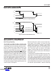
Figure 11. RS232 Receiver Propagation Delays
1.5V
3V
0V
RXEN
f = 1MHz: t
r
≤ 10ns: t
f
≤ 10ns
1.5V
R
V
OL
5V
t
ZL
t
LZ
0.5V
OUTPUT NORMALLY LOW
0V
LTC1387 • F12
1.5V
1.5V
t
ZH
V
OH
OUTPUT NORMALLY HIGH
t
HZ
0.5V
R
Figure 12. Receiver Enable and Disable Times
U
S
A
O
PP
L
IC
AT
I
WU
U
I FOR ATIO
Basic Theory of Operating
The LTC1387 is a single 5V supply, single-port logic
reconfigurable RS485/RS232 transceiver with an onboard
charge pump. The interface port offers a flexible combina-
tion of an RS485 driver and an RS485 receiver or two
RS232 drivers and two RS232 receivers. The RS485
transceiver and the RS232 transceivers are designed to
share the same I/O pins. A logic input 485/232 controls the
selection between RS485 and RS232 transceiver modes.
The RS485 transceiver supports both RS485 and RS422
standards, whereas the RS232 transceivers support both
RS232 and EIA562 standards. With four additional control
inputs: ON, DXEN, RXEN and SLEW, the LTC1387 can
easily be reconfigured via software to adapt to various
communication needs including a one-signal-line RS232
I/O mode. Four examples of interface port connections are
shown in Figures 13 through 16.
Both the interface drivers and the receivers feature three-
state outputs. Driver outputs are forced into high
impedance when the driver is disabled, in the shutdown
mode or with the power off. The driver outputs can be
forced beyond power supply levels without damage up to
±18V. The receiver inputs can withstand ±25V without
damage. The receiver input resistance is typically 24k in
RS485 mode, shutdown mode or power off but drops to
5k in RS232 mode.
In RS485 mode, the DXEN and RXEN control the three-
state outputs of the driver and receiver respectively. The
SLEW input is active during RS485 mode and the logic
level controls the differential driver slew rate. This pin has
an internal 5µA pull-up current source during the RS485
mode. A high logic selects fast differential driver slew rate
and a low logic selects slow slew rate. In slow slew mode,
the maximum signal bandwidth is reduced, minimizing
Downloaded from Arrow.com.Downloaded from Arrow.com.Downloaded from Arrow.com.Downloaded from Arrow.com.Downloaded from Arrow.com.Downloaded from Arrow.com.Downloaded from Arrow.com.Downloaded from Arrow.com.Downloaded from Arrow.com.