
Datasheet

7
LTC1391
sn1391 1391fas
APPLICATIONS INFORMATION
WUU
U
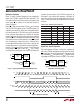
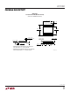
Figure 6. Data Sequence for MUX Expansion
B2 B1 B0
CLK
CS
D
IN
1391 • F06
ENA A2 A1 A0 ENB
12345678
To ensure that only one channel is switched on at any one
time, two sets of channel selection bits are needed for
DATA as shown in Figure 6. The first data sequence is used
to switch off one MUX and the second data sequence is
used to select one channel from the other MUX or
vice versa. In other words, if bit “ENA” is high and bit
“ENB” is low, one channel of MUX A is switched on and all
channels of MUX B are switched off. If bit “ENA” is low and
bit “ENB” is high, all channels at MUX A are switched off
and one channel of MUX B is switched on. Care should be
taken to ensure that only one LTC1391 is enabled at any
one time to prevent two channels from being enabled
simultaneously.
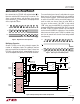
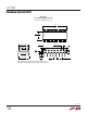
Multiplexer Expansion
Several LTC1391s can be daisy-chained to expand the
number of multiplexer inputs. No additional interface
ports are required for the expansion. Figure 5 shows two
LTC1391s connected at their analog outputs to form a
16-to-1 multiplexer at the input to an LTC1400 A/D converter.
D2D1
D3 D4 D5
D2D1
D3 D4 D5
CLK
D
IN
D
OUT
1391 • F04
1234
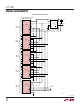
Figure 4. Digital Data Transfer Operation
1
2
3
4
5
6
7
8
16
15
14
13
12
11
10
9
S0
S1
S2
S3
S4
S5
S6
S7
V
+
D
V
–
D
OUT
D
IN
CS
CLK
GND
ANALOG
INPUTS
LTC1391
A
1
2
3
4
8
7
6
5
V
SS
CONV
CLK
D
OUT
V
CC
A
IN
V
REF
GND
LTC1400
1
2
3
4
5
6
7
8
16
15
14
13
12
11
10
9
S0
S1
S2
S3
S4
S5
S6
S7
V
+
D
V
–
D
OUT
D
IN
CS
CLK
GND
LTC1391
B
5V
–5V
–5V
5V
DATA IN
CS
CLK
1391 • F05
0.1µF
ANALOG
INPUTS
0.1µF
10µF
10µF
OPTIONAL A/D
INPUT FILTER
10µF
0.1µF
0.1µF
0.1µF
DATA
OUT
+
+
+
Figure 5. Daisy-Chaining Two LTC1391s for Expansion
bits clocked into the LTC1391 shift register before CS is
taken low select the MUX channel that is turned on. This
allows a series of devices, with the D
OUT
of one device
connected to the D
IN
of the next device, to be programmed
with a single data stream.