
Datasheet


1
LTC1410
12-Bit, 1.25Msps Sampling
A/D Converter with Shutdown
S
F
EA
T
U
RE
D
U
ESCRIPTIO
The LTC
®
1410 is a 0.65µs, 1.25Msps, 12-bit sampling
A/D converter that draws only 160mW from ±5V supplies.
This easy-to-use device includes a high dynamic range
sample-and-hold, a precision reference and requires no
external components. Two digitally selectable power shut-
down modes provide flexibility for low power systems.
The LTC1410’s full-scale input range is ±2.5V. Maximum
DC specifications include ±1LSB INL and ±1LSB DNL over
temperature. Outstanding AC performance includes 71dB
S/(N + D) and 82dB THD at the Nyquist input frequency of
625kHz.
The unique differential input sample-and-hold can acquire
single-ended or differential input signals up to its 20MHz
bandwidth. The 60dB common mode rejection allows
users to eliminate ground loops and common mode noise
by measuring signals differentially from the source.
The ADC has a µP compatible, 12-bit parallel output port.
There is no pipeline delay in the conversion results. A
separate convert start input and a data ready signal (BUSY)
ease connections to FIFOs, DSPs and microprocessors.
■
1.25Msps Sample Rate
■
Power Dissipation: 160mW
■
71dB S/(N + D) and 82dB THD at Nyquist
■
No Pipeline Delay
■
Nap (7mW) and Sleep (10µW) Shutdown Modes
■
Operates with Internal 15ppm/°C Reference
or External Reference
■
True Differential Inputs Reject Common Mode Noise
■
20MHz Full Power Bandwidth Sampling
■
±2.5V Bipolar Input Range
■
28-Pin SO Wide Package
U
S
A
O
PP
L
IC
AT
I
■
Telecommunications
■
Digital Signal Processing
■
Multiplexed Data Acquisition Systems
■
High Speed Data Acquisition
■
Spectrum Analysis
■
Imaging Systems
, LTC and LT are registered trademarks of Linear Technology Corporation.
U
A
O
PP
L
IC
AT
ITY
P
I
CA
L
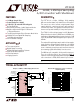
Complete 1.25MHz, 12-Bit Sampling A/D Converter
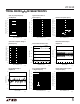
Effective Bits and Signal-to-(Noise + Distortion)
vs Input Frequency
INPUT FREQUENCY (Hz)
2
EFFECTIVE BITS
S/(N + D) (dB)
4
6
8
10
10k 100k 1M 10M
LTC1410 • TA02
0
1k
12 74
68
62
56
50
f
SAMPLE
= 1.25MHz
NYQUIST
1
2
3
4
5
6
7
8
9
10
11
12
13
14
28
27
26
25
24
23
22
21
20
19
18
17
16
15
LTC1410
0.1µF
+
10µF
DIFFERENTIAL
ANALOG INPUT
(–2.5V TO 2.5V)
2.50V
V
REF
OUTPUT
10µF
10µF
0.1µF
0.1µF
–5V
5V
12-BIT
PARALLEL
BUS
µP CONTROL
LINES
1410 TA01
+
+A
IN
–A
IN
V
REF
REFCOMP
AGND
D11(MSB)
D10
D9
D8
D7
D6
D5
D4
DGND
AV
DD
DV
DD
V
SS
BUSY
CS
CONVST
RD
SHDN
NAP/SLP
OGND
D0
D1
D2
D3