
Datasheet

4
LTC1482
SYMBOL PARAMETER CONDITIONS MIN TYP MAX UNITS
t
CDH(SHDN)
Receiver Input to CD Output High at Shutdown R
DIFF
= 54Ω, C
L1
= C
L2
= 100pF, ● 2600 5000 ns
(Figures 4, 11) DI/SHDN = DE
t
CDL(SHDN)
Receiver Input to CD Output Low from Shutdown R
DIFF
= 54Ω, C
L1
= C
L2
= 100pF, ● 2600 5000 ns
(Figures 4, 11) DI/SHDN = DE
t
ZH(SHDN)
Receiver Enable from Shutdown to Output High C
L
= 15pF (Figures 3, 9) S2 Closed, ● 30 600 ns
A = 750mV, B = –750mV, DE = 0,
DI/SHDN =
t
ZL(SHDN)
Receiver Enable from Shutdown to Output Low C
L
= 15pF (Figures 3, 9) S1 Closed, ● 2600 5000 ns
A = –750mV, B = 750mV, DE = 0,
DI/SHDN =
t
HZ(SHDN)
Receiver Disable from High on Shutdown C
L
= 15pF (Figures 3, 9) S2 Closed, ● 200 600 ns
A = 750mV, B = –750mV, DE = 0,
DI/SHDN =
t
LZ(SHDN)
Receiver Disable from Low on Shutdown C
L
= 15pF (Figures 3, 9) S1 Closed, ● 200 600 ns
A = –750mV, B = 750mV, DE = 0,
DI/SHDN =
The ● denotes the specifications which apply over the full operating
temperature range, otherwise specifications are at T
A
= 25°C. V
CC
= 5V ±5% (Notes 2 and 3) unless otherwise noted.
Note 1: Absolute Maximum Ratings are those values beyond which the life of
a device may be impaired.
Note 2: All typicals are given for V
CC
= 5V and T
A
= 25°C.
Note 3: All currents into device pins are positive; all currents out of device
pins are negative. All voltages are referenced to device ground unless
otherwise specified.
Note 4: For higher ambient temperatures, the part may enter thermal
shutdown during short-circuit conditions.
Note 5: Both driver input and driver enable pins are pulled high
simultaneously.
Note 6: Guaranteed by design.
Note 7: Measured with an external LTC1485 driver.
SWITCHING CHARACTERISTICS
U
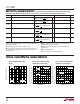
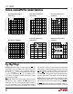
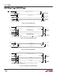
TYPICAL PERFOR A CE CHARACTERISTICS
UW
Receiver Output Voltage vs Input
Voltage
Receiver Input Threshold Voltage
(Output High) vs Temperature
Receiver Input Threshold Voltage
(Output Low) vs Temperature
INPUT VOLTAGE (V)
–0.2
–0.16 –0.12 –0.08 –0.04 0
RECEIVER OUTPUT VOLTAGE (V)
1482 G01
6
5
4
3
2
1
0
T
A
= 25°C
V
THRO(HIGH)
V
THRO(LOW)
TEMPERATURE (°C)
–55 –35 –15 5 25 45 65 85 105 125
RECEIVER INPUT THRESHOLD VOLTAGE (mV)
1482 G02
0
–0.02
–0.04
–0.06
–0.08
–0.1
–0.12
–0.14
–0.16
–0.18
–0.20
V
CC
= 5V
V
THRO(HIGH)
V
CM
= –7V
V
CM
= 12V
V
CM
= 0V
TEMPERATURE (°C)
–55 –35 –15 5 25 45 65 85 105 125
RECEIVER INPUT THRESHOLD VOLTAGE (mV)
1482 G03
0
–0.02
–0.04
–0.06
–0.08
–0.1
–0.12
–0.14
–0.16
–0.18
–0.20
V
CC
= 5V
V
THRO(LOW)
V
CM
= –7V
V
CM
= 12V
V
CM
= 0V