
Datasheet
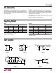

13
LTC1484
R
D
1
1k
RO4 DE4
67
2
58
5V
34
R
D
1
1k
RO2DE2
67
120Ω
2
5
8
5V
5V
34
1.2k
1484 F11
1.2k
120Ω
5V
1.2k
1.2k
R
D
1
1k
RO3
DE3
RO1
DE1
67
2
5
8
5V
34
R
D
1
1k
67
2
5
8
5V
34
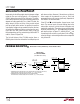
receiver output and expects to see perfect agreement
between the two data streams. (Note that the driver inverts
the data, so the transmitted and received data streams are
actually opposites.) If the simultaneously transmitted and
received data streams differ (usually detected by compar-
ing RO and DE with an XOR), it signals the presence of a
second, active driver. The first driver falls silent, and the
second driver seizes control.
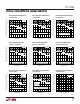
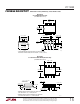
If the LTC1484 is connected as shown in Figure 11, the
overhead of XORing the transmitted and received data in
hardware or software is eliminated. DE and RE are con-
nected together so the receiver is disabled and its output
three-stated whenever a “0” is transmitted. A 1k pull-up
ensures a “1” at the receiver output during this condition.
The receiver is enabled when the driver is disabled. During
this interval the receiver output should also be “1”. Thus,
under normal operation the receiver output is always “1”.
If a “0” is detected, it indicates the presence of a second
active driver attempting to seize control of communica-
tions.
The maximum frequency at which the system in Figure 11
can operate is determined by the cable capacitance, the
values of the pull-up and pull-down resistors and receiver
propagation delay. The external resistors take a longer
time to pull the line to a “1” state due to higher source
resistance compared to an active driver, thereby affecting
the duty cycle of the receiver output at the far end of the
line.
Figure 11. Transmit “0” CDMA Application
APPLICATIONS INFORMATION
WUU
U
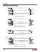
(b)
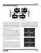
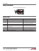
Figure 12a shows a 100kHz DE1 waveform for an LTC1484
driving a 1000-foot shielded twisted-pair (STP) cable and
the A2, B2 and RO2 waveforms of a receiving LTC1484 at
the far end of the cable. The propagation delay between
DE1 of the driver and RO2 at the far end of the line is 1.8µs
at the rising edge and 3.7µs at the falling edge of DE1. The
(a)
Figure 12. LTC1484 Driving a 1000 Foot STP Cable
1484 F12a
1484 F12b
B2
A2
RO2
DE1
DE1
B2
A2
RO2