
Datasheet


7
LTC1485
TI
W
E
WAVEFORS
U
G
WITCHI
W
S
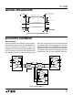
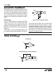
Figure 9. Typical Connection
1.5V
0V
t
ZL
f = 1MHz; t
r
≤ 10ns; t
f
≤ 10ns
V
OL
3V
V
OH
1485 F08
1.5V
t
ZH
RO
RO
1.5V
t
LZ
0.5V
0.5V
t
HZ
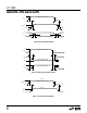
OUTPUT NORMALLY LOW
OUTPUT NORMALLY HIGH
1.5V
0V
5V
RE
Figure 8. Receiver Enable and Disable Times
U
S
A
O
PP
L
IC
AT
I
WU
U
I FOR ATIO
Typical Application
A typical connection of the LTC1485 is shown in Figure 9.
Two twisted pair wires connect up to 32 driver/receiver
pairs for half duplex data transmission. There are no
restrictions on where the chips are connected to the wires
and it isn’t necessary to have the chips connected at the
ends. However, the wires must be terminated only at the
ends with a resistor equal to their characteristic imped-
ance, typically 120Ω. The input impedance of a receiver is
typically 20k to GND, or 0.6 unit RS485 load, so in practice
50 to 60 transceivers can be connected to the same wires.
The optional shields around the twisted pair help reduce
unwanted noise, and are connected to GND at one end.
8
7
120Ω
120Ω
3
4
RX
DX
2
1
1485 F09
LTC1485
RX
DX
4
1
3
2
LTC1485
RECEIVER
RX
DX
7
4
1
3
2
LTC1485
8
RECEIVER
DRIVER
RECEIVER
DRIVER
DRIVER