
Datasheet


8
LTC1485
U
S
A
O
PP
L
IC
AT
I
WU
U
I FOR ATIO
Thermal Shutdown
The LTC1485 has a thermal shutdown feature which
protects the part from excessive power dissipation. If the
outputs of the driver are accidentally shorted to a power
supply or low impedance source, up to 250mA can flow
through the part. The thermal shutdown circuit disables
the driver outputs when the internal temperature reaches
150°C and turns them back on when the temperature
cools to 130°C. If the outputs of two or more LTC1485
drivers are shorted directly, the driver outputs can not
supply enough current to activate the thermal shutdown.
Thus, the thermal shutdown circuit will not prevent con-
tention faults when two drivers are active on the bus at the
same time.
Cables and Data Rate
The transmission line of choice for RS485 applications is
a twisted pair. There are coaxial cables (twinaxial) made
for this purpose that contain straight pairs, but these are
less flexible, more bulky, and more costly than twisted
pairs. Many cable manufacturers offer a broad range of
120Ω cables designed for RS485 applications.
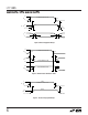
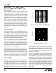
Losses in a transmission line are a complex combination
of DC conductor loss, AC losses (skin effect), leakage, and
AC losses in the dielectric. In good polyethylene cables
such as the Belden 9841, the conductor losses and dielec-
tric losses are of the same order of magnitude, leading to
relatively low overall loss (Figure 10).
When using low loss cables, Figure 11 can be used as a
guideline for choosing the maximum line length for a given
data rate. With lower quality PVC cables the dielectric loss
factor can be 1000 times worse. PVC twisted pairs have
terrible losses at high data rates (>100kbs), and greatly
reduce the maximum cable length. At low data rates
however, they are acceptable and much more economical.
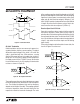
Cable Termination
The proper termination of the cable is very important. If
the cable is not terminated with its characteristic imped-
ance, distorted waveforms will result. In severe cases,
distorted (false) data and nulls will occur. A quick look at
the output of the driver will tell how well the cable is
terminated. It is best to look at a driver connected to the
FREQUENCY (MHz)
0.1
0.1
LOSS PER 100 FT (dB)
1
10
1 10 100
1485 F10
DATA RATE (bps)
10k
10
CABLE LENGTH (FT)
100
1k
10k
100k 1M 10M
1485 F11
2.5M
Figure 11. Cable Length vs Data Rate
Figure 10. Attenuation vs Frequency for Belden 9481
end of the cable, since this eliminates the possibility of
getting reflections from two directions. Simply look at the
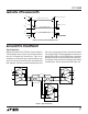
driver output while transmitting square wave data. If the
cable is terminated properly, the waveform will look like
a square wave (Figure 12).
If the cable is loaded excessively (47Ω) the signal initially
sees the surge impedance of the cable and jumps to an
initial amplitude. The signal travels down the cable and is
reflected back out of phase because of the mistermination.
When the reflected signal returns to the driver, the ampli-
tude will be lowered. The width of the pedestal is equal to
twice the electrical length of the cable (about 1.5ns/foot).
If the cable is lightly loaded (470Ω) the signal reflects in
phase and increases the amplitude at the driver output. An
input frequency of 30kHz is adequate for tests out to 4000
feet of cable.