
Datasheet

10
LTC1518/LTC1519
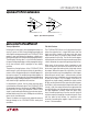
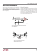
Figure 9 shows a trace with 100ft category 5 UTP between
an LTC1685 driver and an LTC1518 receiver. Notice that at
the far end of the cable, the signal to the LTC1518 input has
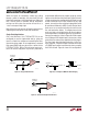
been reduced. Figure 10 shows a 52Mbps square wave.
Output Short-Circuit Protection
The LTC1518/LTC1519 employ voltage sensing short-
circuit protection at the output terminals. For a given input
differential, this circuitry determines what the correct
output level should be. For example, if the input differential
is ≥ 300mV, it expects the output to be a logic high. If the
output is subsequently shorted to a voltage below V
DD
/2,
this circuitry shuts off the output devices and turns on a
smaller device in its place. A timeout period of about 50ns
is used in order to maintain normal high frequency opera-
tion, even under heavy capacitive loads (>100mA tran-
sient current into the load).
Figure 9. 20ns Pulse Propagating Down 100ft of Category 5 UTP
Figure 10. 52Mbps Pulse Train Over 100ft of Category 5 UTP
APPLICATIO S I FOR ATIO
WUUU
50ns/DIV
LTC1518/19 • F09
2V/DIV
2V/DIV
5V/DIV
DRIVER
INPUT
RECEIVER
INPUT
RECEIVER
OUTPUT
CABLE
DELAY
NOTES:
TOP TRACE: LTC1685 DRIVER INPUT
MID TRACE: LTC1518 INPUT AT FAR END
OF 100ft CATAGORY 5 UTP
BOTTOM TRACE: LTC1518 OUTPUT
20ns/DIV
LTC1518/19 • F10
1V/DIV
5V/DIV
RECEIVER
INPUT
RECEIVER
OUTPUT
NOTES:
TOP TRACE: LTC1518 INPUT AT FAR END
OF 100ft CAT 5 UTP
BOTTOM TRACE: LTC1518 OUTPUT