
Datasheet

8
LTC1518/LTC1519
When the inputs are accidentally shorted (by cutting
through a cable, for example), the short-circuit fail-safe
feature will guarantee a high output logic level. Note also
that if the line driver is removed and the termination
resistors are left in place, the receiver will see this as a
“short” and output a logic high.
Both of these fail-safe features will keep the receiver from
outputting false data pulses under fault conditions.
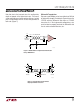
Single-Ended Applications
Over short distances, the LTC1518/LTC1519 can be
configured to receive single-ended data by tying one
input to a fixed bias voltage and connecting the other
input to the driver output. In such applications, standard
high speed CMOS logic may be used as a driver for the
LTC1518/LTC1519. With a 22k minimum input resis-
tance, the receiver trip points may be easily adjusted to
accommodate different driver output swings by chang-
ing the resistor divider at the fixed input. Figure 6a shows
a single-ended receiver configuration with the driver and
receiver connected via PC traces. Note that at very high
speeds, transmission line and driver ringing effects must
be considered. Motorola’s
MECL System Design Hand-
book
serves as an excellent reference for transmission
line and termination effects. To mitigate transmission
errors and duty cycle distortion due to driver ringing, a
small output filter or a dampening resistor on the driver’s
V
DD
may be needed as shown in Figure 6b. With an open
circuit voltage of 3.3V at both inputs, the receivers can be
used without an external bias applied to the fixed inputs.
The fixed input should be bypassed with a 0.01µF ce-
ramic capacitor. The positive input should be driven with
a 5V CMOS part in order to minimize the skew caused by
the 3.3V threshold. Figure 6c shows this configuration.
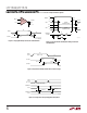
Figure 6a. Single-Ended Receiver
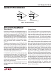
Figure 6b. Techniques to Minimize Driver Ringing
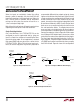
Figure 6c. Self Biased Single Ended Receiver
–
+
2.2k
5V
PC TRACE
1/4
LTC1518
LTC1519
MC74ACT04
(TTL INPUT)
MC74AC04
(CMOS INPUT)
2.2k
1518/19 F06a
0.01µF
10Ω
PC TRACE OR
PC TRACE
0.01µF
MC74AC04
1518/19 F06b
10pF
10Ω
–
+
PC TRACE
1/4
LTC1518
LTC1519
MC74ACT04
(TTL INPUT)
MC74AC04
(CMOS INPUT)
1518/19 F06c
0.01µF
APPLICATIO S I FOR ATIO
WUUU