
Datasheet

LTC1535
10
1535fc
For more information www.linear.com/LTC1535
applicaTions inForMaTion
Isolation Barrier and Sampled Communication
The LTC1535 uses the SW-28 isolated lead frame pack-
age to provide capacitive isolation barrier between the
logic interface and the RS48
5 driver/receiver pair. The
barrier provides 2500V
RMS
of isolation. Communication
between the two sides uses the isolation capacitors in a
multiplexed way to communicate full-duplex data across
this barrier (see Figure 20 and Block Diagram). The data
is sampled and encoded before transmitting across the
isolation barrier, which will add sampling jitter and delay
to the signals (see Figures 13 and 14). The sampling jitter
is approximately 250ns with a nominal delay of 600ns. At
250kBd rate, this represents 6.2% total jitter. The nominal
DE signal to the driver output delay is 875ns ±125ns,
which is longer due to the encoding. Communication
start-up time is approximately 1µs to 2µs. A time-out fault
will occur if communication from the isolated side fails.
Faults can be monitored on the RE pin.
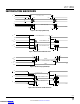
The maximum baud rate can be determined by connect
-
ing in self-oscillation mode as shown in Figure 1. In this
configuration, with SLO = V
CC2
, the oscillation frequency
is set by the internal sample rate. With SLO = 0V, the fre-
quency is reduced by the slower output rise and fall times.
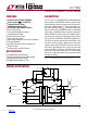
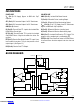
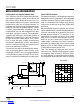
Push-Pull DC/DC Converter
The powered side contains a full-bridge open-loop driver,
optimized for use with a single primary and center-tapped
secondary transformer. Figure 10 shows the DC/DC con-
verter in a configuration that can deliver up to 100mA of
current
to the isolated side using a Eaton CTX02-14659
transformer.
Because the DC/DC converter is open-loop, care in choos-
ing low impedance parts is important for good regulation.
Care must also be taken to not exceed the V
CC2
recom-
mended maximum voltage of 7.5V when there is very
light loading. The isolated side contains a low voltage
detect circuit to ensure that communication across the
barrier will only occur when there is sufficient isolated
supply voltage. If the output of the DC/DC converter is
overloaded, the supply voltage will trip the low voltage
detection at 4.2V. For higher voltage stand-off, the Eaton
CTX02-14608 transformer may be used.
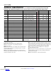
Table 1 lists examples of transformers which are suit
-
able for use in the LTC1535’s DC/DC converter using the
circuit topology shown in Figure 10. While this second-
ary circuit topology is recommended, other secondary
circuit topologies are possible which allows for different
**
2
1
1
1535 F10
V
CC
GND
LOGIC COMMON
2
FLOATING RS485 COMMON ** EATON (888) 414-2645
420kHz
4
1411
1
+
+
GND2
1/2 BAT54C
1/2 BAT54C
I
LOAD
V
CC2
ST1 ST2
32
V
CC
1
10µF
10µF
2
CTX02-14659
I
EXT
I
VCC2
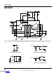
TOTAL LOAD CURRENT, I
LOAD
(mA)
0 50 100 150
V
CC2
(V)
1535 F10a
8
6
4
2
0
V
CC
= 5.5V
V
CC
= 5V
V
CC
= 4.5V
Figure 10
V
CC2
vs I
LOAD
Downloaded from Arrow.com.Downloaded from Arrow.com.Downloaded from Arrow.com.Downloaded from Arrow.com.Downloaded from Arrow.com.Downloaded from Arrow.com.Downloaded from Arrow.com.Downloaded from Arrow.com.Downloaded from Arrow.com.Downloaded from Arrow.com.