
Datasheet

LTC1535
11
1535fc
For more information www.linear.com/LTC1535
applicaTions inForMaTion
transformer configurations. The DC/DC converter driver’s
Thévenin equivalent resistance is approximately 4Ω and
the transformer’s volt-second rating should be greater
than 7µVs.
Driver Output and Slow Slew Rate Control
The LTC1535 uses a proprietary driver output stage
that allows a common mode voltage range that extends
beyond the power supplies. Thus, the high impedance
state is maintained over the full RS485 common mode
range. The output stage provides 100mA of short-circuit
current limiting in both the positive and negative direc-
tions. Thus, even under short-circuit conditions, the sup-
ply voltage from the open-loop DC converter will remain
high
enough for proper communication across the iso-
lation barrier. The driver output will be disabled in the
event of a thermal shutdown and a fault condition will be
indicated through the RE weak output.
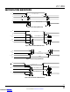
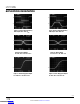
The CMOS level SLO pin selects slow or fast slew rates
on the RS485 driver output (see Figures 15, 16, 17, 18 for
typical waveforms). The SLO input has an internal 100k
pull-up resistor. When SLO is low, the driver outputs are
slew rate limited to reduce high frequency edges. Left
open or tied high, SLO defaults to fast edges. The part
draws more current during slow slew rate edges.
Monitoring Faults on RE
The RE pin can be used to monitor the following fault
conditions: low supply voltages, thermal shutdown or
a time-out fault when there is no data communication
across the barrier. During a fault, the receiver output,
RO, defaults to a high state (see Table 2). Open circuit or
short-circuit conditions on the twisted pair do not cause
a fault indication. However, the RS485 receiver defaults
to a high output state when the receiver input is open or
short-circuited.
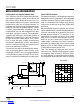
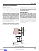
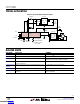
The RE pin has a weak current drive output mode for
indicating fault conditions. This fault state can be polled
using a bidirectional microcontroller I/O line or by using
the circuit in Figure 11, where the control to RE is three-
stated and the fault condition read back from the RE pin.
The weak drive has 100µA pull-up current to indicate a
fault and 50µA pull-down current for no fault. This allows
the RE pin to be polled without disabling RE on nonfault
conditions.
Both sides contain a low voltage detect circuit. A
voltage less than 4.2V on the isolated side disables
communication.
RE
POLL
FAULT
FAULT INDICATED WHEN RE IS THREE-STATED
V
CC
1535 F11
POLL
FAULT
BUFFER
RE
RO
DI
DE
GND
LTC1535
FAULT
V
CC
Figure 11. Detecting Fault Conditions
Downloaded from Arrow.com.Downloaded from Arrow.com.Downloaded from Arrow.com.Downloaded from Arrow.com.Downloaded from Arrow.com.Downloaded from Arrow.com.Downloaded from Arrow.com.Downloaded from Arrow.com.Downloaded from Arrow.com.Downloaded from Arrow.com.Downloaded from Arrow.com.