
Datasheet

LTC1535
7
1535fc
For more information www.linear.com/LTC1535
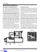
pin FuncTions
POWER SIDE
V
CC
(Pin 1): 5V Supply. Bypass to GND with 10µF
capacitor.
ST1 (Pin 2): DC Converter Output 1 to DC Transformer.
ST2 (Pin 3): DC Converter Output 2 to DC Transformer.
GND (Pin 4): Ground.
DI (Pin 25): Transmit Data TTL Input to the Isolated Side
RS485 Driver. Do not float.
DE (Pin 26): Transmit Enable TTL Input to the Isolated
Side RS485 Driver. A high level enables the driver. Do
not float.
RE (Pin 27): Receive Data Output Enable TTL Input. A low
level enables the receiver. This pin also provides a fault
output signal. (See Figure 11.)
RO (Pin 28): Receive Data TTL Output.
ISOLATED SIDE
GND2 (Pin 11): Isolated Side Power Ground.
Z (Pin 12): Differential Driver Inverting Output.
Y (Pin 13): Differential Driver Noninverting Output.
V
CC2
(Pin 14): 5V to 7.5V Supply from DC Transformer.
Bypass to GND2 with 10µF capacitor.
B (Pin 15): Differential Receiver Inverting Input.
A (Pin 16): Differential Receiver Noninverting Input.
RO2 (Pin 17): Isolated Side Receiver TTL Output. This
output is always enabled and is unaffected by RE.
SLO (Pin 18): Slow Slew Rate Control of RS485 Driver.
A low level forces the driver outputs into slow slew rate
mode.
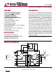
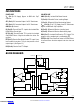
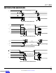
block DiagraM
1
1.3
1.3
POWER SIDE ISOLATED SIDE
D
Y
Z
SLO
100k
V
CC2
27.25k
63.5k
12.75k
27.25k
63.5k
12.75k
DECODE
EN
FAULT
R
A
B
RO2
1535 BD
V
CC
RO
RE
DE
DI
GND
ENCODE
DECODE
420kHz
FAULT
ENCODE
EN
28
27
26
25
4
17
15
16
18
12
13
1411
1
+
GND2 V
CC2
ST1 ST2
32
Downloaded from Arrow.com.Downloaded from Arrow.com.Downloaded from Arrow.com.Downloaded from Arrow.com.Downloaded from Arrow.com.Downloaded from Arrow.com.Downloaded from Arrow.com.