
Datasheet


10
LTC1544
Cable Termination
Traditional implementations have included switching
resistors with expensive relays, or requiring the user to
change termination modules every time the interface
standard has changed. Custom cables have been used
with the termination in the cable head or separate termina-
tions are built on the board and a custom cable routes the
signals to the appropriate termination. Switching the
terminations with FETs is difficult because the FETs must
remain off even though the signal voltage is beyond the
supply voltage for the FET drivers or the power is off.
Using the LTC1344A along with the LTC1543/LTC1544
solves the cable termination switching problem. Via soft-
ware control, the LTC1344A provides termination for the
V.10 (RS423), V.11 (RS422), V.28 (RS232) and V.35
electrical protocols.
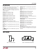
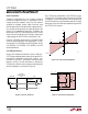
V.10 (RS423) Interface
A typical V.10 unbalanced interface is shown in Figure 11.
A V.10 single-ended generator output A with ground C is
connected to a differential receiver with inputs A' con-
nected to A, and input C' connected to the signal return
ground C. Usually, no cable termination is required for
V.10 interfaces, but the receiver inputs must be compliant
with the impedance curve shown in Figure 12.
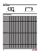
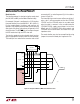
The V.10 receiver configuration in the LTC1544 is shown
in Figure 13. In V.10 mode switch S3 inside the LTC1544
is turned off.The noninverting input is disconnected inside
the LTC1544 receiver and connected to ground. The cable
termination is then the 30k input impedance to ground of
the LTC1544 V.10 receiver.
I
Z
V
Z
–10V
–3.25mA
3.25mA
–3V
3V 10V
1544 F12
Figure 12. V.10 Receiver Input Impedance
Figure 11. Typical V.10 Interface
Figure 13. V.10 Receiver Configuration
AA
'
CC
'
GENERATOR
BALANCED
INTERCONNECTING
CABLE
LOAD
CABLE
TERMINATION
RECEIVER
1544 F11
R5
20k
LTC1544
RECEIVER
1544 F13
A
B
A
'
B
'
C
'
R8
6k
S3
R6
10k
R7
10k
GND
R4
20k
APPLICATIONS INFORMATION
WUU
U