
Datasheet


12
LTC1544
A
A
'
B
C
B
'
C
'
GENERATOR
BALANCED
INTERCONNECTING
CABLE
LOAD
CABLE
TERMINATION
RECEIVER
1544 F18
50Ω
125Ω
50Ω
50Ω
125Ω
50Ω
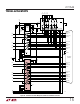
Figure 18. Typical V.35 Interface
R3
124Ω
R5
20k
LTC1344A
LTC1543
RECEIVER
1544 F19
A
B
A
'
B
'
C
'
R1
51.5Ω
R8
6k
S2
S3
R2
51.5Ω
R6
10k
R7
10k
GND
R4
20k
S1
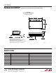
Figure 19. V.35 Receiver Configuration
V.35 Interface
A typical V.35 balanced interface is shown in Figure 18. A
V.35 differential generator with outputs A and B with
ground C is connected to a differential receiver with
ground C', inputs A' connected to A, B' connected to B. The
V.35 interface requires a T or delta network termination at
the receiver end and the generator end. The receiver
differential impedance measured at the connector must be
100Ω␣ ±10Ω, and the impedance between shorted termi-
nals (A' and B') and ground C' must be 150Ω ±15Ω.
In V.35 mode, both switches S1 and S2 inside the LTC1344A
are on, connecting the T network impedance as shown in
Figure 19. The switch in the LTC1543 is off. The 30k input
impedance of the receiver is placed in parallel with the T
network termination, but does not affect the overall input
impedance significantly.
APPLICATIONS INFORMATION
WUU
U