
Datasheet


13
LTC1544
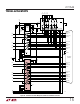
Charge Pump
The LTC1543 uses an internal capacitive charge pump to
generate V
DD
and V
EE
as shown in Figure 21. A voltage
doubler generates about 8V on V
DD
and a voltage inverter
generates about –7.5V for V
EE
. Four 1µF surface mounted
tantalum or ceramic capacitors are required for C1, C2, C3
and C4. The V
EE
capacitor C5 should be a minimum of
3.3µF. All capacitors are 16V and should be placed as close
as possible to the LTC1543 to reduce EMI.
The generator differential impedance must be 50Ω to
150Ω and the impedance between shorted terminals (A
and B) and ground C must be 150Ω ±15Ω. For the
generator termination, switches S1 and S2 are both on and
the top side of the center resistor is brought out to a pin so
it can be bypassed with an external capacitor to reduce
common mode noise as shown in Figure 20.
Figure 20. V.35 Driver Using the LTC1344A
V.35 DRIVER
A
B
C
51.5Ω
S2
ON
S1
ON
1544 F20
51.5Ω
LTC1344A
124Ω
C1
100pF
28
27
26
25
1544 F21
3
2
1
4
C3
1µF
C4
1µF
5V
C1
1µF
C2
1µF
C5
3.3µF
LTC1543
V
DD
C1
+
C1
–
V
CC
C2
+
C2
–
V
EE
GND
+
Figure 21. Charge Pump
Any mismatch in the driver rise and fall times or skew in
the driver propagation delays will force current through
the center termination resistor to ground, causing a high
frequency common mode spike on the A and B terminals.
The common mode spike can cause EMI problems that are
reduced by capacitor C1 which shunts much of the com-
mon mode energy to ground rather than down the cable.
No-Cable Mode
The no-cable mode (M0 = M1 = M2 = 1) is intended for the
case when the cable is disconnected from the connector.
The charge pump, bias circuitry, drivers and receivers are
turned off, the driver outputs are forced into a high
impedance state, and the supply current drops to less than
200µA.
Receiver Fail-Safe
All LTC1543/LTC1544 receivers feature fail-safe opera-
tion in all modes. If the receiver inputs are left floating or
shorted together by a termination resistor, the receiver
output will always be forced to a logic high.
DTE vs DCE Operation
The DCE/DTE pin acts as an enable for Driver 3/Receiver
1 in the LTC1543, and Driver 3/Receiver 1 and Driver 4/
Receiver 4 in the LTC1544. The INVERT pin in the LTC1544
allows the Driver 4/Receiver 4 enable to be high or low true
polarity.
APPLICATIONS INFORMATION
WUU
U