
Datasheet

12
LTC1546
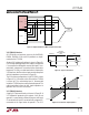
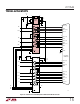
interface has a differential termination at the receiver end
that has a minimum value of 100Ω. The termination
resistor is optional in the V.11 specification, but for the
high speed clock and data lines, the termination is essen-
tial to prevent reflections from corrupting the data. The
receiver inputs must also be compliant with the imped-
ance curve shown in Figure 20.
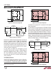
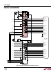
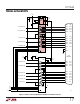
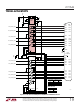
In V.11 mode, all switches are off except S1 of the
LTC1546’s receivers which connects a 103Ω differential
termination impedance to the cable as shown in Figure
23
1
. The LTC1544 only handles control signals, so no
termination other than its V.11 receivers’ 30k input imped-
ance is necessary.
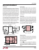
V.28 (RS232) Interface
A typical V.28 unbalanced interface is shown in Figure 24.
A V.28 single-ended generator with output A and ground
C is connected to a single-ended receiver with input A'
Figure 22. Typical V.11 Interface
Figure 21. V.10 Receiver Configuration
R5
20k
LTC1544
RECEIVER
1546 F21
A
B
A
'
B'
C'
R8
6k
S3
R6
10k
R7
10k
GND
R4
20k
AA'
B
C
B'
C'
GENERATOR
BALANCED
INTERCONNECTING
CABLE
LOAD
CABLE
TERMINATION
RECEIVER
100Ω
MIN
1546 F22
Figure 24. Typical V.28 Interface
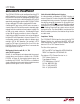
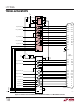
Figure 25. V.28 Receiver Configuration
Figure 23. V.11 Receiver Configuration
R3
124Ω
R5
20k
LTC1546
RECEIVER
1546 F23
A
'
B
'
C
'
R1
51.5Ω
R8
6k
S2
S3
R2
51.5Ω
R6
10k
R7
10k
GND
R4
20k
S1
connected to A and ground C' connected via the signal
return to ground C.
In V.28 mode, S3 is closed inside the LTC1546/LTC1544
which connects a 6k (R8) impedance to ground in parallel
with 20k (R5) plus 10k (R6) for a combined impedance of
5k as shown in Figure 25. Proper termination is only pro-
vided when the B input of the receivers is floating, since S1
of the LTC1546’s R2 and R3 receivers remains on in V.28
mode
1
. The noninverting input is disconnected inside the
LTC1546/LTC1544 receiver and connected to a TTL level
reference voltage to give a 1.4V receiver trip point.
AA
'
CC
'
GENERATOR
BALANCED
INTERCONNECTING
CABLE
LOAD
CABLE
TERMINATION
RECEIVER
1546 F24
R3
124Ω
R5
20k
LTC1546
RECEIVER
1546 F25
A
'
B
'
C
'
R1
51.5Ω
R8
6k
S2
S3
R2
51.5Ω
R6
10k
R7
10k
GND
R4
20k
S1
1
Actually, there is no switch S1 in receivers R2 and R3. However, for simplicity, all termination
networks on the LTC1546 can be treated identically if it is assumed that an S1 switch exists and is
always closed on the R2 and R3 receivers.
APPLICATIO S I FOR ATIO
WUUU