
Datasheet

14
LTC1546
The LTC1546/LTC1544 can be configured for either DTE
or DCE operation in one of two ways: a dedicated DTE or
DCE port with a connector of appropriate gender or a port
with one connector that can be configured for DTE or DCE
operation by rerouting the signals to the LTC1546/LTC1544
using a dedicated DTE cable or dedicated DCE cable.
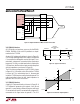
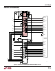
A dedicated DTE port using a DB-25 male connector is
shown in Figure 29. The interface mode is selected by logic
outputs from the controller or from jumpers to either V
CC
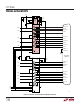
or GND on the mode select pins. A dedicated DCE port
using a DB-25 female connector is shown in Figure 30.
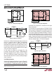
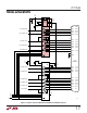
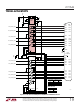
A port with one DB-25 connector, that can be configured
for either DTE or DCE operation is shown in Figure 31. The
configuration requires separate cables for proper signal
routing in DTE or DCE operation. For example, in DTE
mode, the TXD signal is routed to Pins 2 and 14 via the
LTC1546’s Driver 1. In DCE mode, Driver 1 now routes the
RXD signal to Pins 2 and 14.
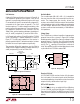
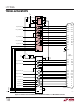
Multiprotocol Interface with RL, LL, TM
and a DB-25 Connector
If the RL, LL and TM signals are implemented, there are not
enough drivers and receivers available in the LTC1546/
LTC1544. In Figure 32, the required control signals are
handled by the LTC1545. The LTC1545 has an additional
single-ended driver/receiver pair that can handle two more
optional control signals such as TM and RL.
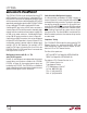
Cable-Selectable Multiprotocol Interface
A cable-selectable multiprotocol DTE/DCE interface is
shown in Figure 33. The select lines M0, M1 and DCE/DTE
are brought out to the connector. The mode is selected by
the cable by wiring M0 (connector Pin 18) and M1 (con-
nector Pin 21) and DCE/DTE (connector Pin 25) to ground
(connector Pin 7) or letting them float. If M0, M1 or DCE/
DTE is floating, internal pull-up current sources will pull
the signals to V
CC
. The select bit M2 is hard wired to V
CC
.
When the cable is pulled out, the interface will go into the
no-cable mode.
Compliance Testing
The LTC1546/LTC1544 chipset has been tested by TUV
Telecom Services Inc. and passed the NET1, NET2 and
TBR2 requirements. Copies of the test reports are avail-
able from LTC or TUV Telecom Services.
The titles of the reports are:
NET1 and NET2: Test Report No. NET2/091301/99.
TBR2: Test Report No. CRT2/091301/99.
The address of TUV Telecom Services Inc. is:
TUV Telecom Services Inc.
Type Approval Division
1775 Old Highway 8, Ste 107
St. Paul, MN 55112 USA
TEL: +1 (612) 639-0775
FAX: +1 (612) 639-0873
APPLICATIO S I FOR ATIO
WUUU