
Datasheet


10
LTC1605
1605fc
APPLICATIONS INFORMATION
WUU
U
signal is applied to the input of the ADC and the resulting
output codes are collected over a large number of conver-
sions. For example in Figure 7 the distribution of output
code is shown for a DC input that has been digitized 10000
times. The distribution is Gaussian and the RMS code
transition is about 1LSB.
Timing and Control
Conversion start and data read are controlled by two
digital inputs: CS and R/C. To start a conversion and put
the sample-and-hold into the hold mode bring CS and
R/C low for no less than 40ns. Once initiated it cannot be
restarted until the conversion is complete. Converter
status is indicated by the BUSY output and this is low while
the conversion is in progress.
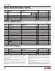
There are two modes of operation. The first mode is shown
in Figure 8. The digital input R/C is used to control the start
of conversion. CS is tied low. When R/C goes low the
sample-and-hold goes into the hold mode and a conver-
sion is started. BUSY goes low and stays low during the
conversion and will go back high after the conversion has
been completed and the internal output shift registers
have been updated. R/C should remain low for no less than
40ns. During the time R/C is low the digital outputs are in
a Hi-Z state. R/C should be brought back high within 3µs
after the start of the conversion to ensure that no errors
occur in the digitized result. The second mode, shown in
Figure 9, uses the CS signal to control the start of a
conversion and the reading of the digital output. In this
mode the R/C input signal should be brought low no less
than 10ns before the falling edge of CS. The minimum
pulse width for CS is 40ns. When CS falls, BUSY goes low
and will stay low until the end of the conversion. BUSY will
go high after the conversion has been completed. The new
data is valid when CS is brought back low again to initiate
Figure 8. Conversion Timing with Outputs Enabled After Conversion (CS Tied Low)
CODE
0
500
1500
1000
2500
2000
4000
3500
3000
4500
COUNT
1605 • F07
–5–4–3–2–1012345
Figure 7. Histogram for 10000 Conversions
DIGITAL INTERFACE
Internal Clock
The ADC has an internal clock that is trimmed to achieve
a typical conversion time of 7µs. No external adjustments
are required and, with the typical acquisition time of 1µs,
throughput performance of 100ksps is assured.
t
1
t
11
t
2
t
4
t
3
t
7
t
6
ACQUIRE CONVERT CONVERTACQUIRE
t
5
t
8
t
ACQ
t
CONV
t
9
PREVIOUS
DATA VALID
PREVIOUS
DATA VALID
HI-Z NOT VALID HI-Z
DATA
VALID
DATA
VALID
R/C
BUSY
MODE
DATA MODE
1605 • F08