
Datasheet


6
LTC1605
1605fc
TYPICAL PERFORMANCE CHARACTERISTICS
U
W
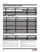
LTC1605 Nonaveraged 4096 Point FFT Plot
FREQUENCY (kHz)
–130
–120
–100
–110
–80
–90
–20
–40
–60
0
–30
–50
–70
–10
MAGNITUDE (dB)
1605 • TPC07
0 5 10 15 20 25 30 35 40 45 50
f
SAMPLE
= 100kHz
f
IN
= 1kHz
SINAD = 87.5dB
THD = –101.7dB
SINAD vs Input Frequency
INPUT FREQUENCY (kHz)
1
SINAD (dB)
90
89
88
87
86
85
84
83
82
81
10 100
1605 • TPC08
Total Harmonic Distortion vs
Input Frequency
INPUT FREQUENCY (kHz)
1
TOTAL HARMONIC DISTORTION (dB)
–70
–80
–90
–100
–110
10 100
1605 • TPC09
PIN FUNCTIONS
UUU
V
IN
(Pin 1): Analog Input. Connect through a 200Ω
resistor to the analog input. Full-scale input range is
±10V.
AGND1 (Pin 2): Analog Ground. Tie to analog ground
plane.
REF (Pin 3): 2.5V Reference Output. Bypass with 2.2µF
tantalum capacitor. Can be driven with an external refer-
ence.
CAP (Pin 4): Reference Buffer Output. Bypass with 2.2µF
tantalum capacitor.
AGND2 (Pin 5): Analog Ground. Tie to analog ground
plane.
D15 to D8 (Pins 6 to 13): Three-State Data Outputs.
Hi-Z state when CS is high or when R/C is low.
DGND (Pin 14): Digital Ground.
D7 to D0 (Pins 15 to 22): Three-State Data Outputs.
Hi-Z state when CS is high or when R/C is low.
BYTE (Pin 23): Byte Select. With BYTE low, data will be
output with Pin 6 (D15) being the MSB and Pin 22 (D0)
being the LSB. With BYTE high the upper eight bits and
the lower eight bits will be switched. The MSB is output