
Datasheet


7
LTC1629-6
16296f
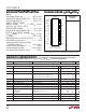
RUN/SS (Pin 1): Combination of Soft-Start, Run Control
Input and Short-Circuit Detection Timer. A capacitor to
ground at this pin sets the ramp time to full current output.
Forcing this pin below 0.8V causes the IC to shut down all
internal circuitry. All functions are disabled in shutdown.
SENSE1
+
, SENSE2
+
(Pins 2,14): The (+) Input to the
Differential Current Comparators. The I
TH
pin voltage and
built-in offsets between SENSE
–
and SENSE
+
pins in
conjunction with R
SENSE
set the current trip threshold.
SENSE1
–
, SENSE2
–
(Pins 3, 13): The (–) Input to the
Differential Current Comparators.
EAIN (Pin 4): Input to the Error Amplifier that compares
the feedback voltage to the internal 0.6V reference voltage.
This pin is normally connected to a resistive divider from
the output of the differential amplifier (DIFFOUT).
PLLFLTR (Pin 5): The Phase-Locked Loop’s Low Pass
Filter is tied to this pin. Alternatively, this pin can be driven
with an AC or DC voltage source to vary the frequency of
the internal oscillator.
PI FU CTIO S
UUU
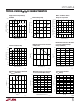
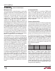
Current Sense Pin Input Current
vs Temperature
EXTV
CC
Switch Resistance
vs Temperature
Oscillator Frequency
vs Temperature
Undervoltage Lockout
vs Temperature
Shutdown Latch Thresholds
vs Temperature
TYPICAL PERFOR A CE CHARACTERISTICS
UW
TEMPERATURE (°C)
–50 –25
0
SHUTDOWN LATCH THRESHOLDS (V)
0.5
1.5
2.0
2.5
75 10050
4.5
1629 G27
1.0
0 25 125
3.0
3.5
4.0
LATCH ARMING
LATCHOFF
THRESHOLD
TEMPERATURE (°C)
–50
UNDERVOLTAGE LOCKOUT (V)
3.40
3.45
3.50
25 75
1629 G26
3.35
3.30
–25 0
50 100 125
3.25
3.20
TEMPERATURE (°C)
–50
200
250
350
25 75
1629 G25
150
100
–25 0
50 100 125
50
0
300
FREQUENCY (kHz)
V
PLLFLTR
= 2.4V
V
PLLFLTR
= 0V
TEMPERATURE (°C)
–50 –25
0
EXTV
CC
SWITCH RESISTANCE (Ω)
4
10
0
50
75
1629 G24
2
8
6
25
100
125
TEMPERATURE (°C)
–50 –25
25
CURRENT SENSE INPUT CURRENT (µA)
29
35
0
50
75
1629 G23
27
33
31
25
100
125
V
OUT
= 5V