
Datasheet


11
LTC1686/LTC1687
APPLICATIONS INFORMATION
WUU
U
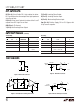
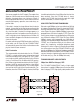
Figure 15a. 1.6Mbps, 8000 Feet (1.5 Miles) Using Three Repeaters
2V/DIV
5V/DIV
2V/DIV
5V/DIV
DRIVER 1
INPUT
RECEIVER 5
OUTPUT
DRIVER 1
INPUT
RECEIVER 5
OUTPUT
1686/87 F15b
2µs/DIV
DELAY OF 8000 FT
OF CABLE
goes above or below the rails. It is advisable to terminate
the PC traces when approaching maximum speeds. Since
the LTC1686/LTC1687 are not intended to drive parallel
terminated cables with characteristic impedances much
less than that of twisted pair, both ends of the PC trace
must be
series terminated
with the characteristic imped-
ance of the trace. For best results, the signal should be
routed differentially. The true and complement outputs of
the LTC1686/LTC1687 should be routed on adjacent lay-
ers of the PC board. The two traces should be routed very
symmetrically, minimizing and equalizing parasitics to
nearby signal and power/ground layers. For single-ended
transmission, route the series terminated single-ended
trace over an adjacent ground plane. Then set the (by-
passed) negative input of the receiver to roughly 2.5V.
Note that single-ended operation might not reach maxi-
mum speeds.
LAYOUT CONSIDERATIONS
A ground plane is recommended when using high fre-
quency devices like the LTC1686/LTC1687. A 0.1µF ce-
ramic bypass capacitor less than 0.25 inch away from the
V
DD
pin is also recommended.
propagation of a 600ns pulse through the network of
Figure 15A. The bottom two traces show a 1.6Mbps
square wave. Notice that the duty cycle does not notice-
ably degrade. For the case of the single pulse, however,
there is a slight degradation of the pulse width.
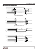
By slowing down the data rate slightly to 1Mbps, one can
obtain minimal pulse width degradation as the signal
traverses through the repeater network. Figure 16 shows
that the output pulse (bottom trace) is nearly the same
width to the input pulse (top trace). The middle three
traces of Figure 16 show the signal at the end of each of the
first three 2000 feet sections of category 5 UTP. Notice
how the LTC1687 repeaters are able to regenerate the
signal with little loss. This implies that we can cascade
more repeater networks and potentially achieve 1Mbps
operation at total distances of over 10,000 feet! A higher
data rate can be achieved if the repeaters are spaced closer
together.
HIGH SPEED BACKPLANE TRANSMISSION
The LTC1686/LTC1687 can also be used in backplane
point-to-point transceiver applications, where the user
wants to assure operation even when the common mode
2V/DIV
1V/DIV
1V/DIV
1V/DIV
5V/DIV
DRIVER 1
INPUT
RECEIVER 2
INPUT
RECEIVER 3
INPUT
RECEIVER 4
INPUT
RECEIVER 5
OUTPUT
1686/87 F16
2µs/DIV
Figure 15b. 1.6Mbps Pulse and Square Wave Signals
Over 8000 Feet Category 5 UTP Using Three Repeaters
Figure 16. Intermediate Signals of a 1µs Pulse
Information furnished by Linear Technology Corporation is believed to be accurate and reliable.
However, no responsibility is assumed for its use. Linear Technology Corporation makes no represen-
tation that the interconnection of its circuits as described herein will not infringe on existing patent rights.
LTC1687
LTC1687
REPEATER
2000 FT 2000 FT 2000 FT 2000 FT
1686/87 F15a
LTC1687
REPEATER
LTC1687
REPEATER
LTC1687
D R5R4DR3DR2D1
R