
Datasheet

8
LTC1690
3
1
5
6
D
120Ω
2
1
8
7
RDRIVER
LTC1690
5V
LTC1690
RECEIVER
120Ω
SHIELD
2
4
7
8
R
3
4
6
5
DRECEIVER DRIVER
1690 F06
SHIELD
0.01µF
5V
0.01µF
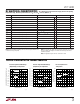
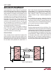
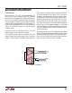
Figure 6. Typical Application
APPLICATIONS INFORMATION
WUU
U
A typical application is shown in Figure 6. Two twisted pair
wires connect two driver/receiver pairs for full duplex data
transmission. Note that the driver and receiver outputs are
always enabled. If the outputs must be disabled, use the
LTC491. There are no restrictions on where the chips are
connected, and it isn’t necessary to have the chips con-
nected to the ends of the wire. However, the wires must be
terminated at the ends with a resistor equal to their
characteristic impedance, typically 120Ω. Because only
one driver can be connected on the bus, the cable need
only be terminated at the receiving end. The optional
shields around the twisted pair are connected to GND at
one end and help reduce unwanted noise.
The LTC1690 can be used as a line repeater as shown in
Figure 7. If the cable is longer that 4000 feet, the LTC1690
is inserted in the middle of the cable with the receiver
output connected back to the driver input.
Receiver Fail-Safe
Some encoding schemes require that the output of the
receiver maintains a known state (usually a logic 1) when
data transmission ends and all drivers on the line are
forced into three-state. The receiver of the LTC1690 has a
fail-safe feature which guarantees the output to be in a
logic 1 state when the receiver inputs are left floating or
shorted together. This is achieved without external com-
ponents by designing the trip-point of the LTC1690 to be
within –200mV to –10mV. If the receiver output must be
a logic 0 instead of a logic 1, external components are
required.
The LTC1690 fail-safe receiver is designed to reject fast
–7V to 12V common mode steps at its inputs. The slew
rate that the receiver will reject is typically 400V/µs, but
–7V to 12V steps in 10ns can be tolerated if the frequency
of the common mode step is moderate (<600kHz).
Driver-Receiver Crosstalk
The driver outputs generate fast rise and fall times. If the
LTC1690 receiver inputs are not terminated and floating,
switching noise from the LTC1690 driver can couple into
the receiver inputs and cause the receiver output to glitch.
This can be prevented by ensuring that the receiver inputs
are terminated with a 100Ω or 120Ω resistor, depending
on the type of cable used. A cable capacitance that is
greater than 10pF (≈1ft of cable) also prevents glitches if
no termination is present. The receiver inputs should not
be driven typically above 8MHz to prevent glitches.